Eighteen pulse rectification scheme for use with variable frequency drives

a variable frequency drive and pulse rectifier technology, applied in the field of eighteen pulse rectifiers, can solve problems such as voltage distortion, current distortion becomes an important issue, current harmonic distortion,

Inactive Publication Date: 2008-07-10
YASKAWA ELECTRIC AMERICA
View PDF8 Cites 29 Cited by
  • Summary
  • Abstract
  • Description
  • Claims
  • Application Information

AI Technical Summary

Problems solved by technology

This results in current harmonic distortion, which eventually translates into voltage distortion.
However, in cases where the majority of the load on a distribution feeder is made up of Variable Frequency Drives with rectifier front ends, the current distortion becomes an important issue.
Harmonics can have a detrimental effect on emergency generators, telephones and other electrical equipment.
When reactive power compensation (in the form of passive power factor improving capacitors) is used with non-linear loads, resonance conditions can occur that may result in even higher levels of harmonic voltage and current distortion thereby causing equipment failure and disruption of power service.
Harmonic distortion concerns are serious when the power ratings of the VFD load increases.
Use of large power VFDs increases the amplitude of low order harmonics that can significantly impact the power system.
In many large power installations, current harmonic distortion levels achievable using twelve-pulse techniques are insufficient to meet the levels recommended in IEEE Standard 519-1992.
One disadvantage of the scheme shown in FIG. 1 is that the phase-shifting isolation transformer is bulky and expensive.
This can potentially stress the DC bus capacitors and the IGBTs in the inverter section of a VFD.
These windings not only add cost and increase the overall rating of the transformer, but also cause imbalance that results in higher than normal circulating currents in the delta windings, which need to be accommodated.
Similar to the previous configuration, the stub winding currents are high and the teaser winding needs to carry rated load current making the overall transformer big in size and expensive to wind.
Use of stub windings typically results in poor utilization of the core and involves more labor to wind the coils.
Initially, the windmill structure was present in each phase and the size of the transformer was still big.
In the eighteen-pulse autotransformer systems, the change of current from one conducting diode pair to the other is quite sudden.
Since the use of autotransformer systems with eighteen-pulse operation is, recent, there is not much statistical data available to comment on the di / dt issue with diodes when used in conjunction with eighteen-pulse autotransformer techniques.
Some important drawbacks of the topologies discussed in the prior art are as follows:a. Autotransformer based topologies require significant input impedance to smooth the current and reduce the overall input current distortion,b. Autotransformer techniques utilize complex winding structures, either of the stub-type or the polygon type.
These transformers are labor intensive to manufacture and result in poor core utilization,c. Because of complicated winding structure and the fact that partial turns are not practically feasible to build, the error resulting in rounding off can be significant that influences the final performance.

Method used


Image

  • Eighteen pulse rectification scheme for use with variable frequency drives
  • Eighteen pulse rectification scheme for use with variable frequency drives
  • Eighteen pulse rectification scheme for use with variable frequency drives

Examples


Embodiment Construction

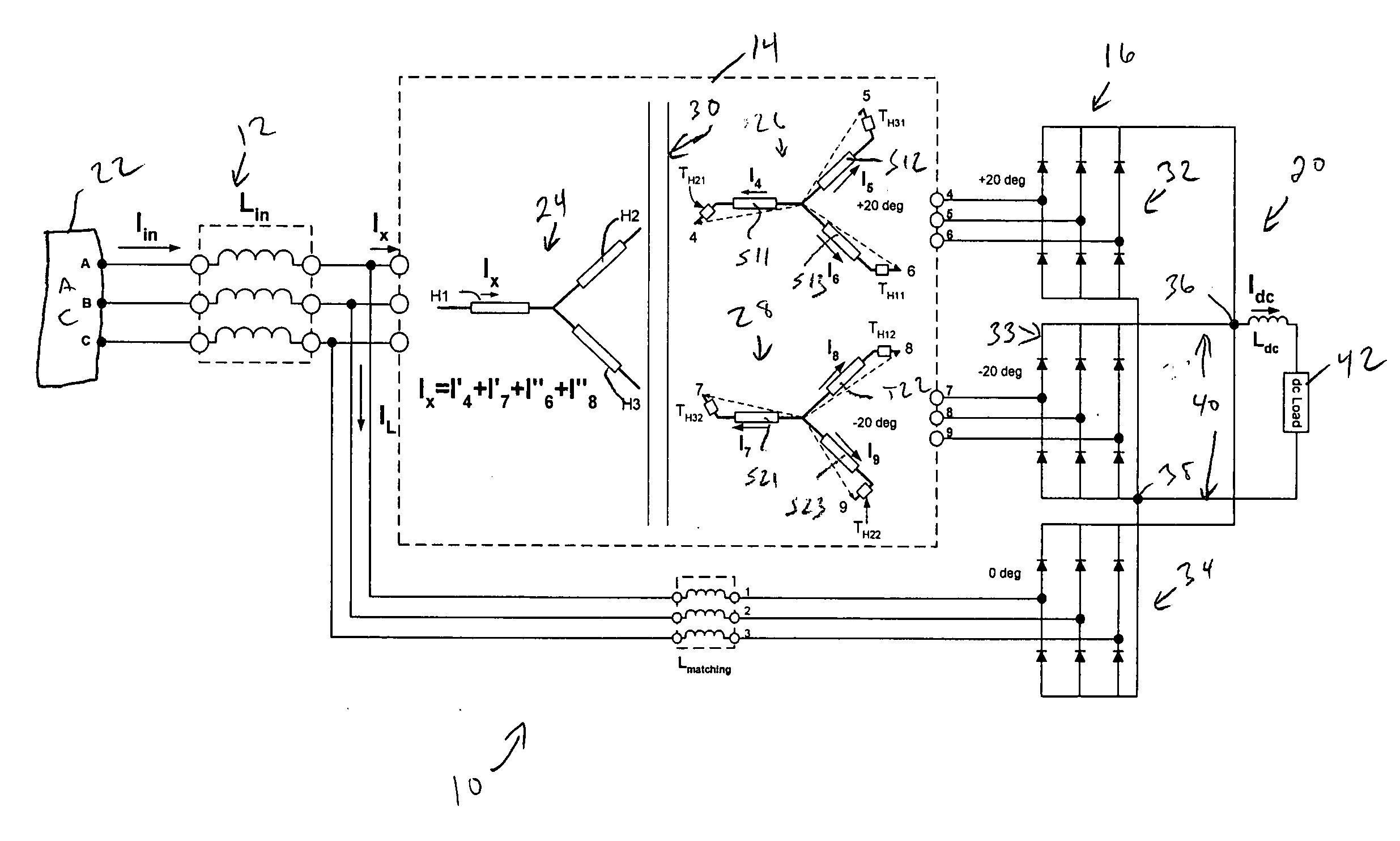
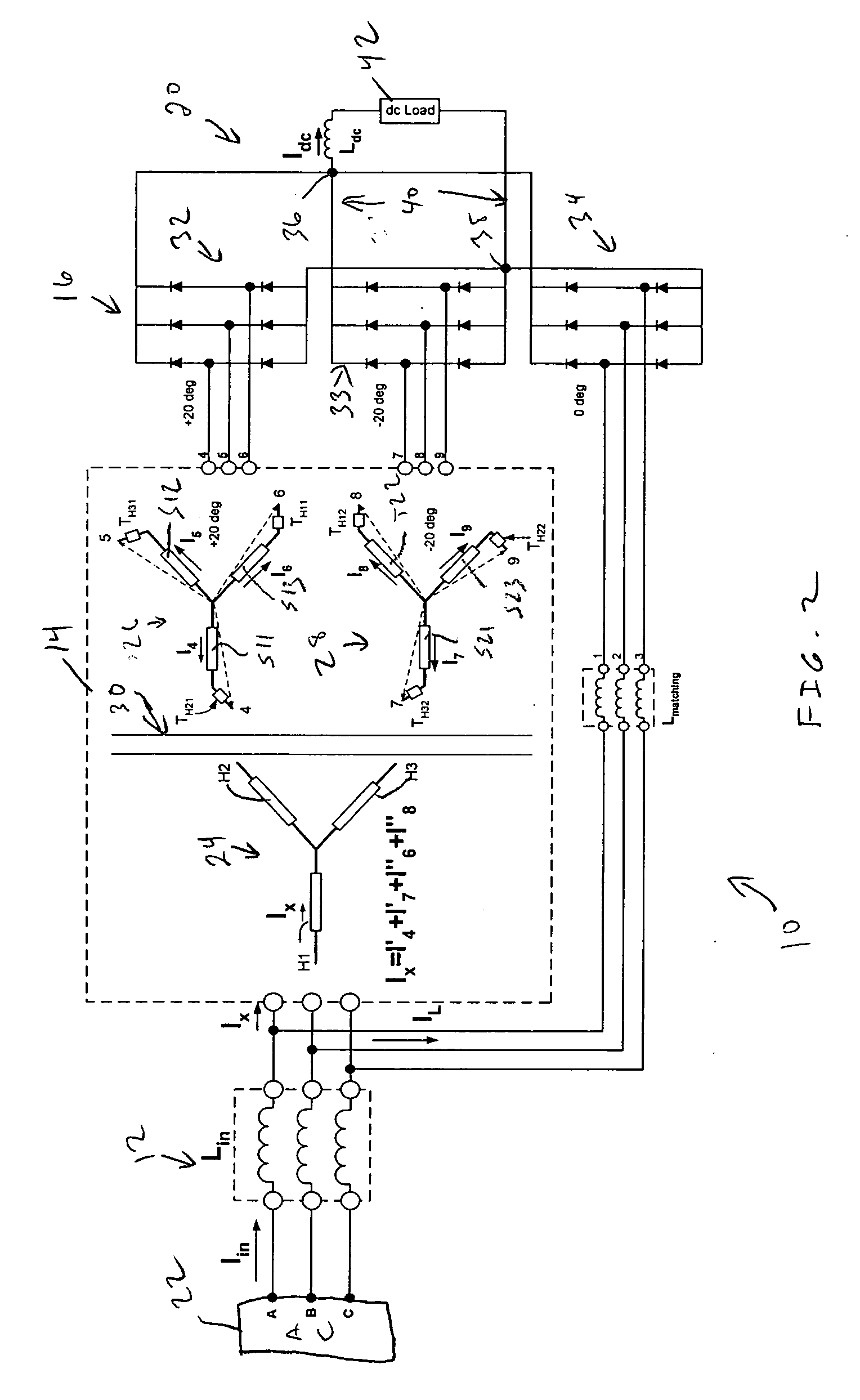
[0035]In accordance with the invention, an isolation transformer uses two sets of secondary windings, reducing size and cost. An eighteen-pulse rectifier uses one six-pulse rectifier circuit directly connected to the AC source via some balancing inductance to match the inductance in front of the other two sets of six-pulse rectifier circuits to achieve eighteen-pulse operation.

[0036]The resulting scheme has two six-pulse rectifiers powered via a phase-shifting isolation transformer, while the third six-pulse rectifier is fed directly from the AC source via a matching-impedance. Such an eighteen-pulse arrangement is shown in FIG. 2. The phase-shifting transformer feeding two of the three six-pulse rectifiers is sized to handle ⅔rd the rated power. Similarly, the matching inductor is sized to carry only ⅓rd the rated current. This arrangement results in the overall size of the transformer and matching inductor combination to be smaller and less expensive than the four winding arrangem...


PUM


Abstract

An AC / DC converter system comprises an input circuit for connection to a three phase AC source. An isolation transformer comprises a set of primary windings and first and second sets of secondary windings magnetically coupled to the set of primary windings. The first and second sets of secondary windings are phase shifted by select amounts from the set of primary windings. The set of primary windings is connected to the input circuit. An AC / DC converter comprises first, second and third three phase rectifiers, the first three phase rectifier being powered by the first set of secondary windings, the second three phase rectifier being powered by the second set of secondary windings, and the third three phase rectifier being powered by the input circuit. An impedance matching inductor is electrically connected between the input circuit and the third three phase rectifier. An output circuit is connected between the AC / DC converter and a DC load.

Description

CROSS REFERENCE TO RELATED APPLICATIONS[0001]There are no related applications.FIELD OF THE INVENTION[0002]The present invention relates to an AC / DC converter system and, more particularly, to an eighteen pulse rectifier using an isolation transformer with two sets of secondary windings.BACKGROUND OF THE INVENTION[0003]Variable Frequency Drive (VFD) systems with diode rectifier front ends draw discontinuous current from the power system to which they are connected. This results in current harmonic distortion, which eventually translates into voltage distortion. Typically, the power system is robust and can handle significant amount of current distortion without showing signs of voltage distortion. However, in cases where the majority of the load on a distribution feeder is made up of Variable Frequency Drives with rectifier front ends, the current distortion becomes an important issue. Grid-connected transformers run hotter under harmonic loading. Harmonics can have a detrimental ef...

Claims


Application Information

Patent Timeline
Patent Type & Authority Applications(United States)
IPC IPC(8): H02M7/04H02M7/06
CPCH02M7/08
Inventor SWAMY, MAHESH M.
Owner YASKAWA ELECTRIC AMERICA
Why Eureka
Try Eureka