Architecture for image compression in a video hardware

a video hardware and image compression technology, applied in the field of image compression and decompression, can solve the problems of large energy consumption, large transmission and equipment requirements, and limited battery capacity and siz of image capture devices, and achieve the effect of facilitating image decompression

Inactive Publication Date: 2008-07-10
HUMAN MONITORING
View PDF32 Cites 36 Cited by
  • Summary
  • Abstract
  • Description
  • Claims
  • Application Information

AI Technical Summary

Benefits of technology

[0049](b) modifying the code to facilitat...

Problems solved by technology

Transferring a multi-mega pixels image may place a large demand on transmission and equipment and energy consum...

Method used


Image

  • Architecture for image compression in a video hardware
  • Architecture for image compression in a video hardware
  • Architecture for image compression in a video hardware

Examples


example i

Video Apparatus Example I

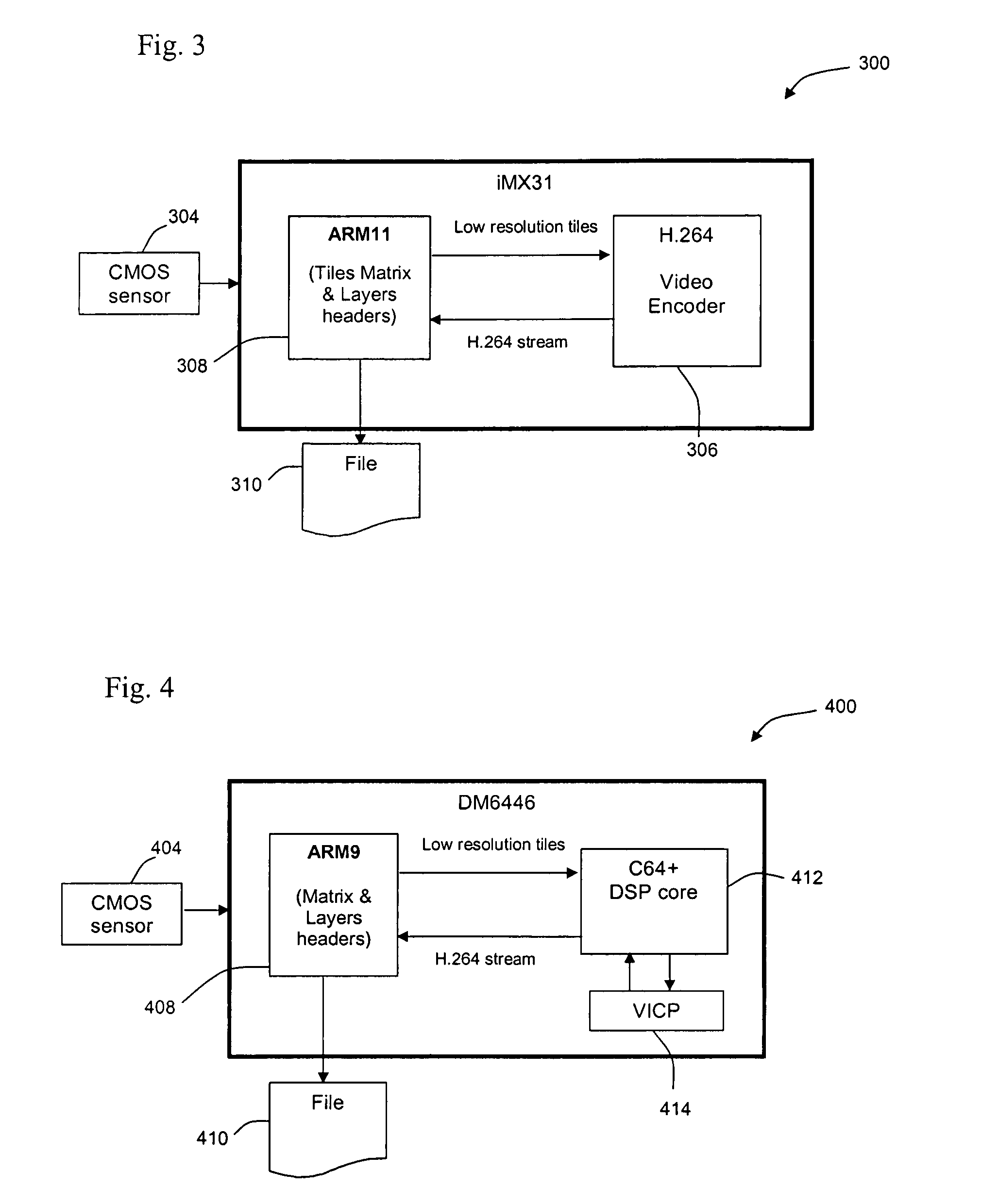
[0160]FIG. 3 schematically illustrates an implementation of Freescale Semiconductor of iMX31 apparatus 300 for compressing an image using a video compression apparatus, in accordance with exemplary embodiments of the invention. Apparatus 300 is a simplification of a device described in Freescale Semiconductor i.MX31 and i.MX31L Multimedia Applications Processors Product Brief (Document Number. MCIMX31PB Rev. 1, February 2006), the disclosure of which is incorporated herein by reference.

[0161]The iMX31 architecture comprises an ARM11 (RISC processor) core 308 and a H.264 video encoder 306 capable of encoding frames in D1 or lower resolution.

[0162]With reference to and comparison with apparatus 100 and 200 of FIGS. 1 and 2 and their respective operation, in some embodiments of the invention ARM11 core 308 receives a high resolution still image from a CMOS (or CCD) imager 304. The image is received at ARM11 core 308 in a BAYER format or YUV format. ARM11 core 3...

example ii

Video Apparatus Example II

[0168]FIG. 4 schematically illustrates a Texas Instruments TMS320DM6446 (‘DM6446’) apparatus 400 for compressing an image using a video compression apparatus, in accordance with exemplary embodiments of the invention. Apparatus 400 is a simplification of a device described in Texas Instruments TMS320DM6446 Digital Media System-on-Chip (SPRS283E—December 2005—Revised March 2007), the disclosure of which is incorporated herein by reference.

[0169]The DM6446 architecture comprises an ARM9 (RISC processor) core 408, a C64+ DSP core 412 and a video and imaging coprocessor (VICP) 414.

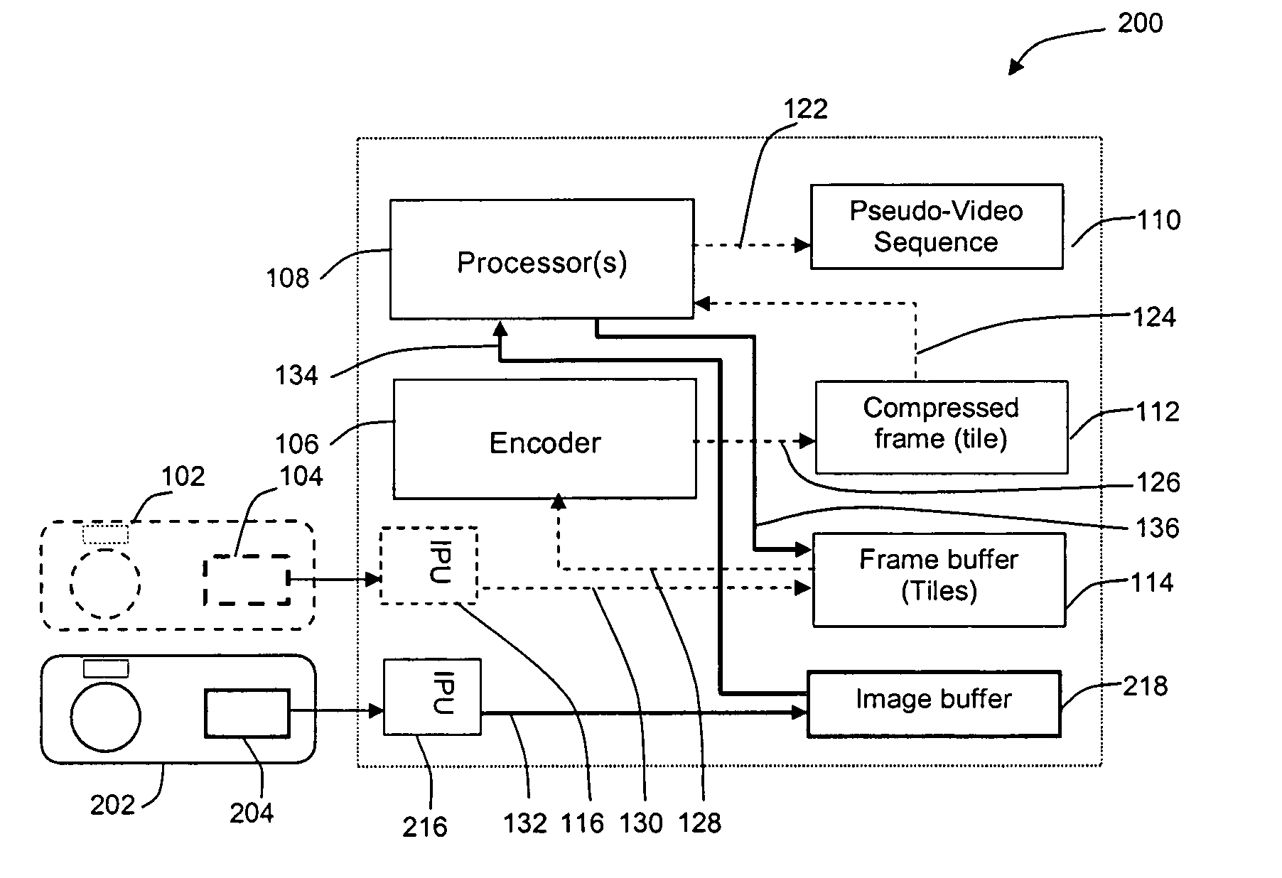
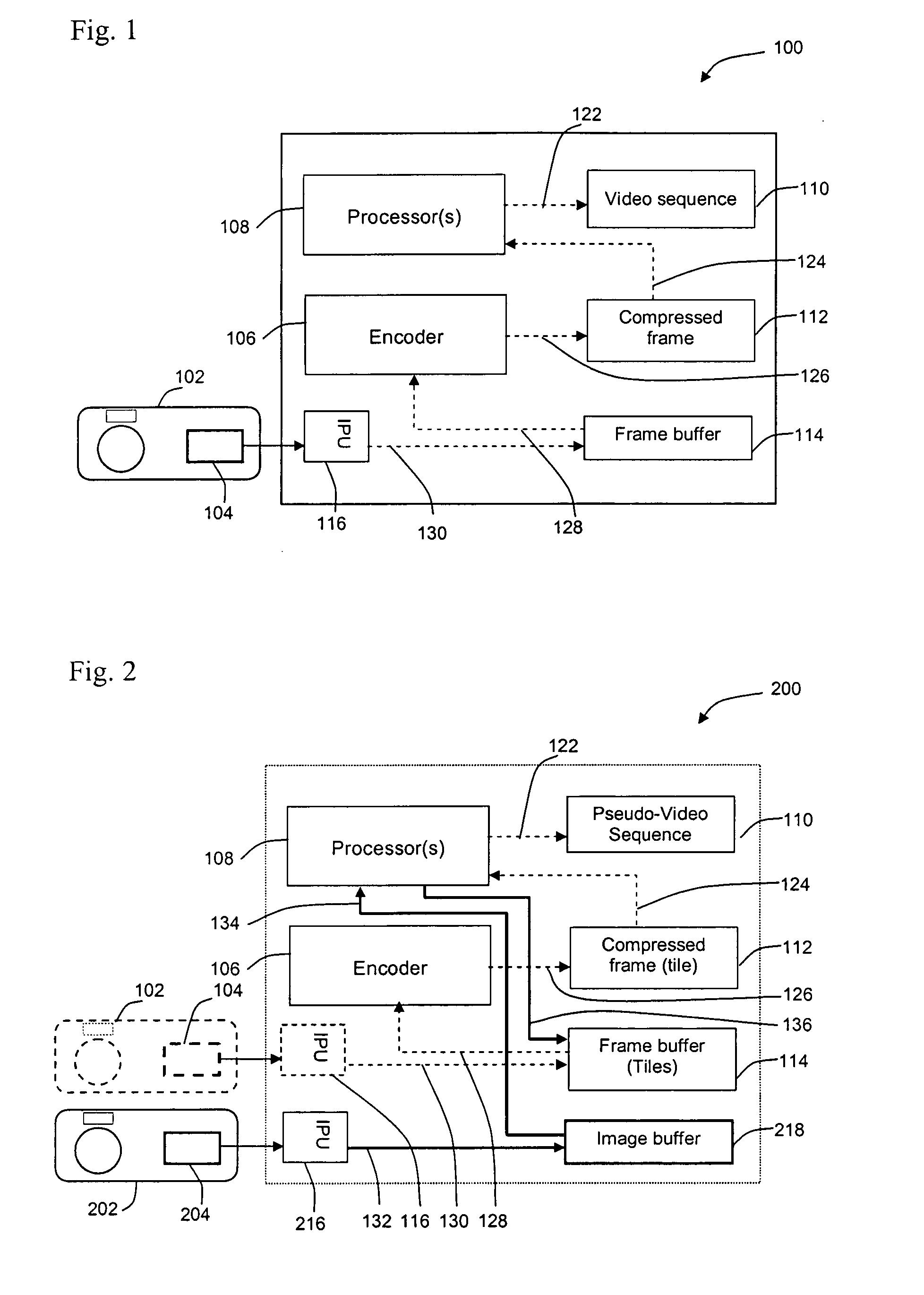
[0170]With reference to and comparison with apparatus 100 and 200 of FIGS. 1 and 2 and their respective operation, in some embodiments of the invention ARM9 core 408 receives a high resolution still image from a CMOS (or CCD) imager 404. ARM9 core 408 partitions the image into tiles which are sent to DSP core 412 for encoding into a compressed pseudo-video sequence, where DSP core 412...


PUM


Abstract

A method for compressing an image in a sequence of pseudo-video frames of a lower resolution than the image, comprising providing a video encoder fit for at least one of a spatial or temporal compression, providing an image, dividing the image into a plurality of partitions and encoding the partitions into pseudo-video frames by the encoder.

Description

RELATED APPLICATIONS[0001]This application is a continuation-in-part of U.S. patent application Ser. No. 11 / 882,811 filed on Aug. 6, 2007, which claims the benefit under 35 USC 119(e) of U.S. Provisional Patent Applications Nos. 60 / 878,062 and 60 / 878,063, both filed on Jan. 3, 2007.[0002]This application also relates to U.S. patent application Ser. No. 11 / 987,639 filed on Dec. 3, 2007.[0003]This application is also being co-filed with the following PCT Patent Applications:[0004]Attorney docket No. 37635 entitled “ARCHITECTURE FOR IMAGE COMPRESSION IN A VIDEO HARDWARE”.[0005]Attorney docket No. 37636 entitled “ENTROPY DEFICIENCY BASED IMAGE COMPRESSION”.[0006]Attorney docket No. 42975 entitled “COMPRESSING HIGH RESOLUTION IMAGES AS A LOW RESOLUTION VIDEO”.[0007]The disclosures of all the cited applications are incorporated herein by reference.FIELD OF THE INVENTION[0008]This invention, in some embodiments thereof, relates to image compression and decompression. Some embodiments relat...

Claims


Application Information

Patent Timeline
IPC IPC(8): H04B1/66
CPCH04N19/61H04N19/436H04N19/42
Inventor DVIR, IRARABINOWITZ, NITZAN
Owner HUMAN MONITORING
Why Eureka
Try Eureka