[0024]It is configured in each of the first, second, fourth, sixth, and eighth aspects of the present invention such that the degree of refrigerant leakage in the expansion valve (52) is estimated from a result of detection taken by the high-low
pressure difference detection means (93, 97). Therefore, based on a result of detection taken by the high-low pressure difference detection means (93, 97), the control means (81) sets the reference temperature (T3) (which serves as a threshold for determining termination of the ice melting operation) to a value corresponding to the degree of refrigerant leakage in the expansion valve (52). In the past, the reference temperature (T3) has been decided without taking into consideration the leakage of refrigerant in the expansion valve (52). In the present invention, however, the reference temperature (T3) is set to a value corresponding to the degree of refrigerant leakage in the expansion valve (52), whereby, even in the event of occurrence of refrigerant leakage from the expansion valve (52), it is possible to determine termination of the ice melting operation at the reference temperature (T3) corresponding to the refrigerant leakage. Accordingly, it becomes possible to accurately determine termination of the ice melting operation, regardless of the presence or absence of refrigerant leakage in the expansion valve (52). This therefore makes it possible to prevent the ice melting operation from being unnecessarily executed while also preventing some ice from remaining unmelted.
[0025]Additionally, it is configured in the second aspect of the present invention such that an estimate of the degree of degradation of the expansion valve (52) is derived from a difference between the value of measurement taken by the
temperature measurement means (54) and the value of measurement taken by the
room temperature measurement means (56) during suspension of the cooling operation. Therefore, the control means (81) corrects, by use of a correction value corresponding to the degree of degradation of the expansion valve (52), the reference temperature (T3) set based on the value of measurement taken by the high-low pressure difference detection means (93, 97). The degree of degradation of the expansion valve (52) has an effect on the degree of refrigerant leakage in the expansion valve (52) during the ice melting operation, like when the cooling operation is under suspension. The second aspect of the present invention uses a correction value corresponding to the degree of degradation of the expansion valve (52) to correct the reference temperature (T3), and the reference temperature (T3) comes to have a value that reflects the degree of degradation of the expansion valve (52). Accordingly, it becomes possible to more accurately determine termination of the ice melting operation.
[0026]In addition, it is configured in the third aspect of the present invention such that an estimate of the degree of degradation of the expansion valve (52) is derived from a difference between the value of measurement taken by the
temperature measurement means (54) and the value of measurement taken by the
room temperature measurement means (56). Therefore, based on the measured value difference, the control means (81) sets the reference temperature (T3) serving as a threshold for determining termination of the ice melting operation to a value corresponding to the degree of degradation of the expansion valve (52). The expansion valve (52) is liable to undergo leakage of refrigerant therefrom when degraded. In the third aspect of the present invention, however, the reference temperature (T3) is set to a value corresponding to the degree of degradation of the expansion valve (52), whereby, even in the case where there is leakage of refrigerant due to degradation of the expansion valve (52), it is possible to determine termination of the ice melting operation at the reference temperature (T3) corresponding to that valve degradation. Accordingly, even in the case where there is leakage of refrigerant due to degradation of the expansion valve (52), it is possible to accurately determine termination of the ice melting operation. This therefore makes it possible to prevent the ice melting operation from being unnecessarily executed while also preventing some ice from remaining unmelted.
[0027]In addition, it is configured in the fourth aspect of the present invention such that an estimate of the degree of meltability of ice adhering to the utilization-side heat exchanger (53) is derived from a difference between the value of measurement taken by the
temperature measurement means (54) and the value of measurement taken by the
room temperature measurement means (56). Therefore, based on the measured value difference, the control means (81) sets the reference time (t3) to a value corresponding to the estimated degree of meltability. In the past, the ice melting operation has been brought to a halt according to the fixed reference time (t3), regardless of the degree of meltability of the adhered ice. In the fourth aspect of the present invention, however, the reference time (t3) is set to a value corresponding to the degree of meltability of the adhered ice, because the time required for melting of the adhered ice varies depending on the degree of meltability of the adhered ice. This therefore makes it possible to more accurately determine termination of the ice melting operation.
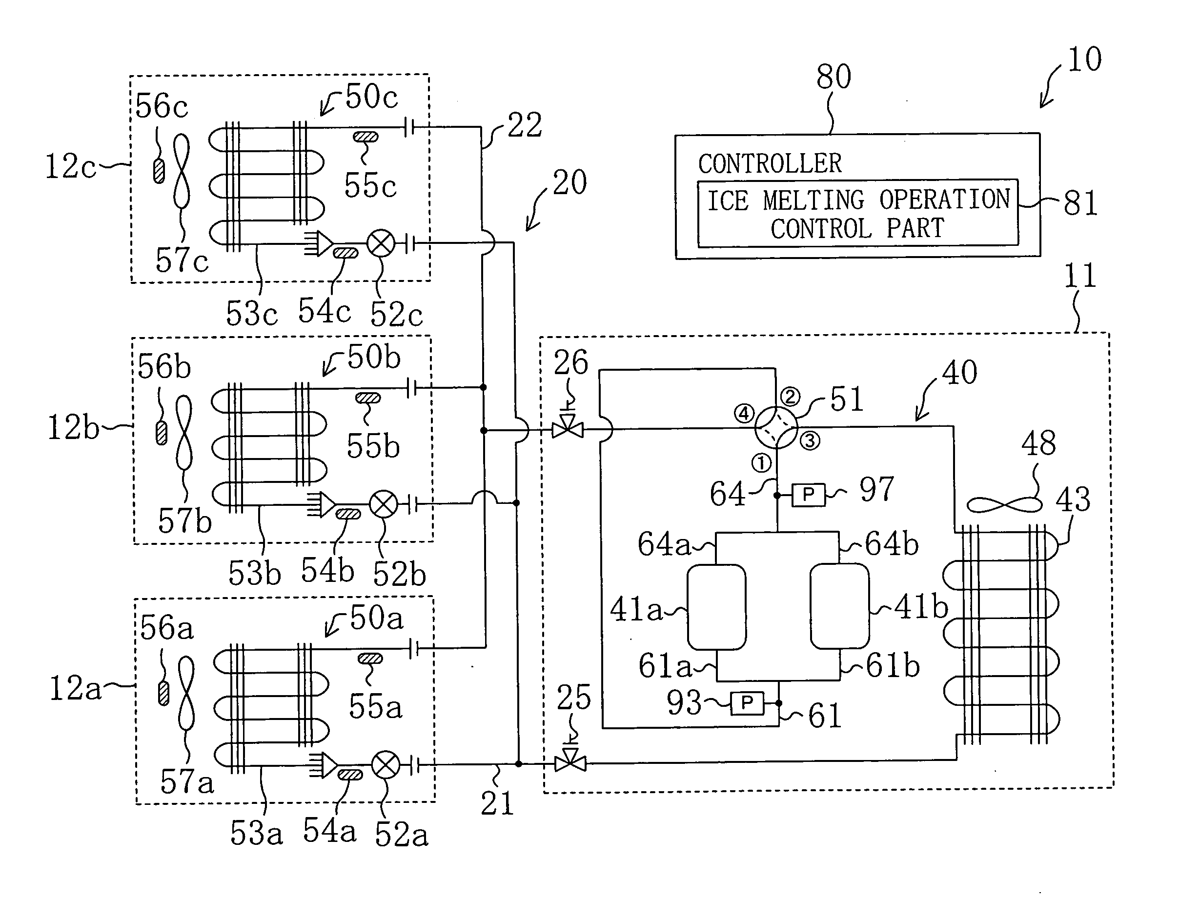
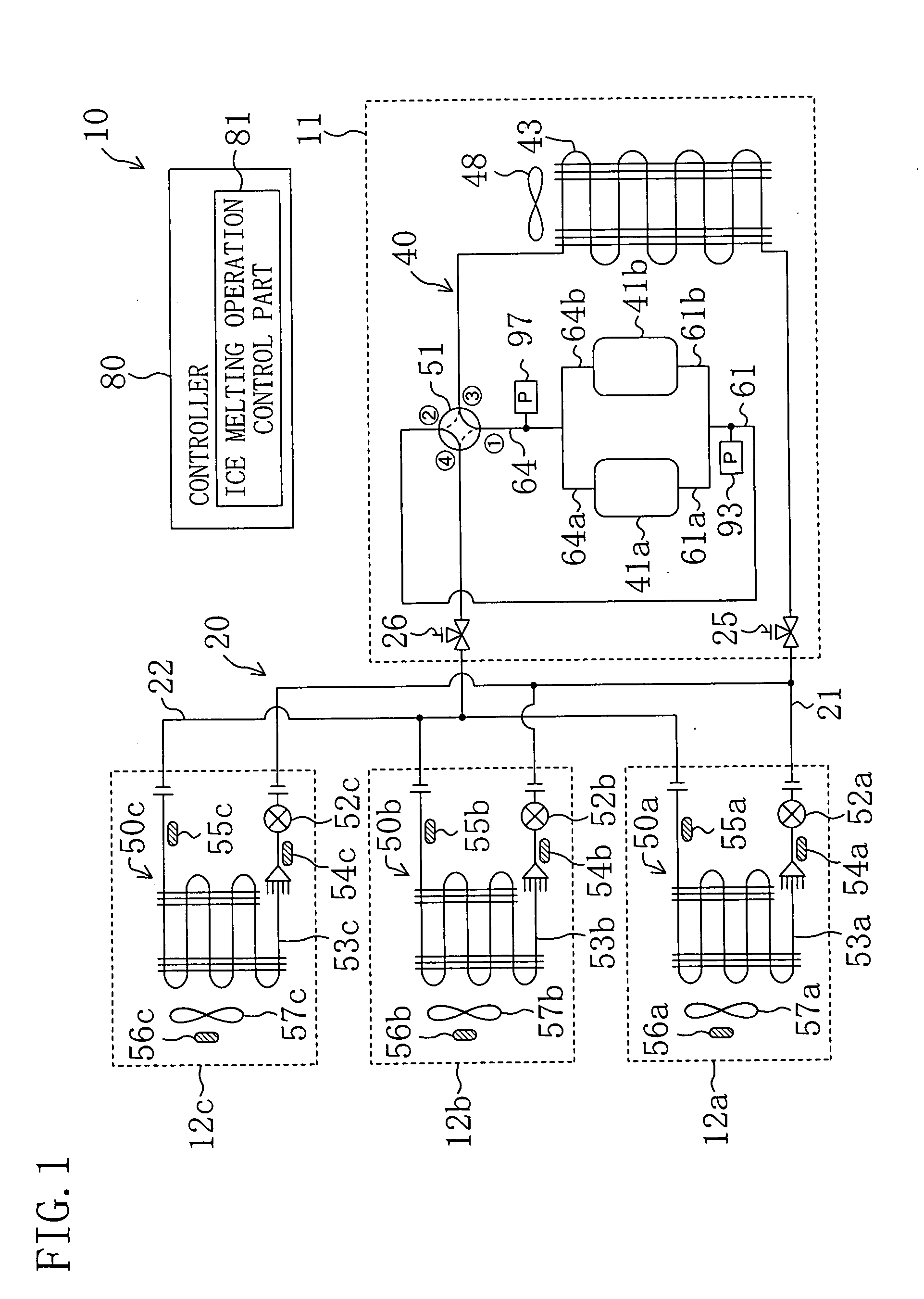
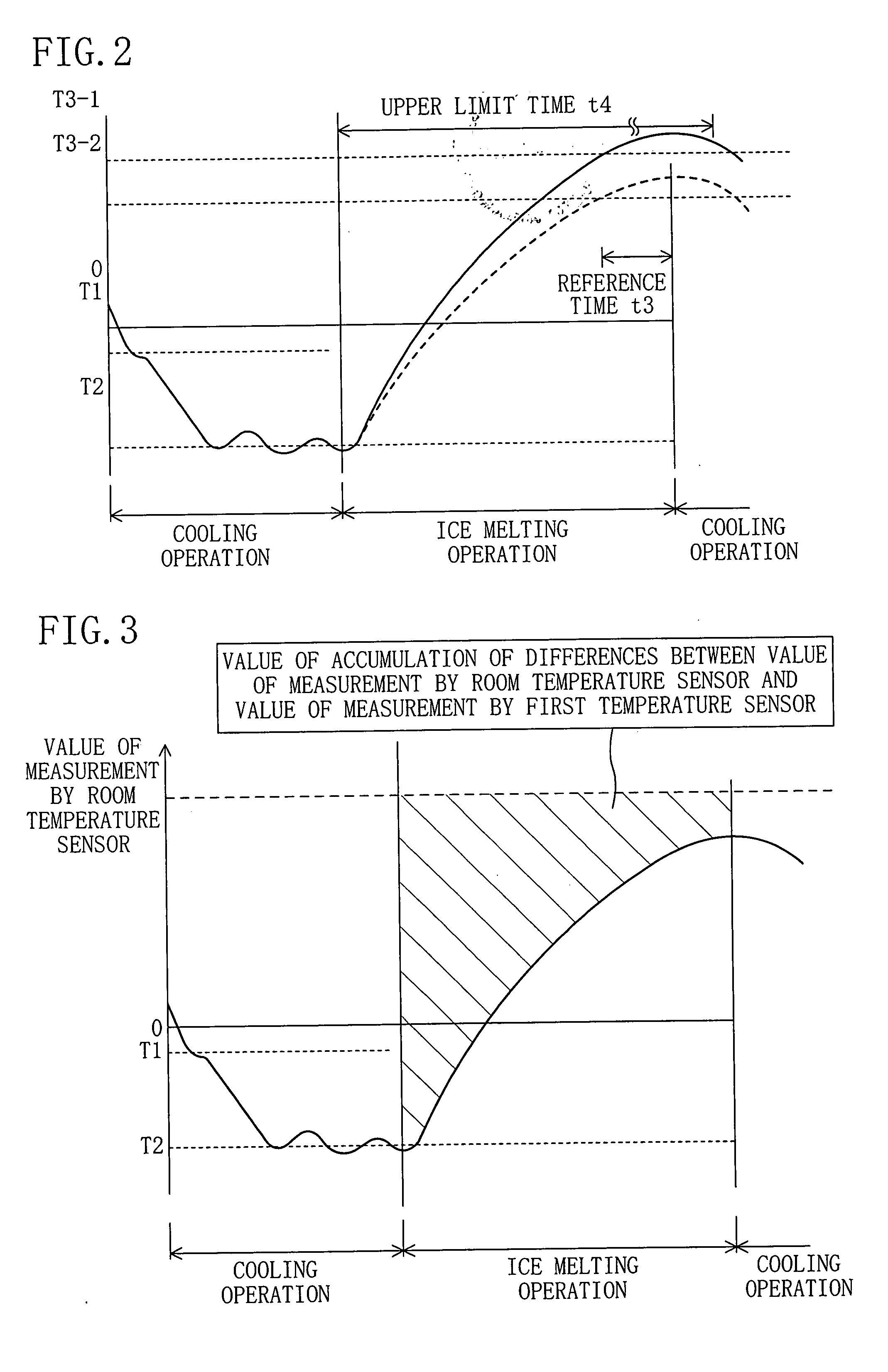
[0028]Additionally, it is configured in the fifth aspect of the present invention such that the value of accumulation of differences between the value of measurement taken by the temperature measurement means (54) and the value of measurement taken by the room temperature measurement means (56), which permits an estimate of the amount of heat exchanged between air fed into the utilization-side heat exchanger (53) and ice adhering to the utilization-side heat exchanger (53) during execution of the ice melting operation, is used to determine termination of the ice melting operation. The amount of heat exchange estimated from the accumulation value corresponds to the amount of melted ice. This therefore makes it possible to estimate, from the accumulation value, whether or not a predetermined amount of ice has been melted, whereby it becomes possible to accurately determine termination of the ice melting operation. In addition, it is configured in the fifth aspect of the present invention such that, even in the case where there is leakage of refrigerant, the increase in the value of accumulation of differences between the value of measurement taken by the temperature measurement means (54) and the value of measurement taken by the room temperature measurement means (56) will not be impeded. This therefore eliminates the problem associated with the conventional technology that the air conditioner fails to return to its normal cooling operation from the ice melting operation due to refrigerant leakage in the expansion valve (52). Consequently, it becomes possible to prevent the ice melting operation from being unnecessarily executed while also preventing some ice from remaining unmelted.
[0029]In addition, it is configured in the sixth aspect of the present invention such that an estimate of the degree of meltability of ice adhering to the utilization-side heat exchanger (53) is derived from a difference between the value of measurement taken by the temperature measurement means (54) and the value of measurement taken by the room temperature measurement means (56). Therefore, based on the measured value difference, the control means (81) sets the upper
limit time (t4) to a value corresponding to the estimated degree of meltability. The control means (81) determines termination of the ice melting operation, not only from the condition that the value of measurement taken by the temperature measurement means (54) continuously remains equal to or above the reference temperature (T3) for the reference time (t3) but also from the upper
limit time (t4) which is set to a value corresponding to the estimated degree of meltability. This therefore makes it possible to more accurately determine termination of the ice melting operation.

