Magnetic key for use with a security device

Inactive Publication Date: 2008-07-17
INVUE SECURITY PROD INC
View PDF20 Cites 26 Cited by
  • Summary
  • Abstract
  • Description
  • Claims
  • Application Information

AI Technical Summary

Benefits of technology

[0013]The magnetic key of the present invention comprises a housing in which a dipole magnet is movably engaged. The dipole magnet is movable between a first retracted position where substantially the entire magnet is retained within the housing, and a second extended position where the magnet extends outwardly from the housing. The dipole magnet is formed into a pattern or shape that is complementary to a specifically designed or patterned recess formed in the security device. The shape of the dipole magnet and recess is such that the magnet can only enter the recess in one specific orientation. Furthermore, the dipole magnet is configured so as to bring only the necessary and appropriate north or south poles of the magnet into the proximity of the locking mechanism within the body of the security device. Finally, a dipole magnet is manufactured to be substantially stronger than a non-dipole, over-the-counter magnet of substantially the same size, and therefore has a stronger magnetic force field emanating from the body of the

Problems solved by technology

The security devices disclosed in these applications include magnetically attractable locking systems that are contained within an interior chamber of the device and a

Method used


Image

  • Magnetic key for use with a security device
  • Magnetic key for use with a security device
  • Magnetic key for use with a security device

Examples


Embodiment Construction

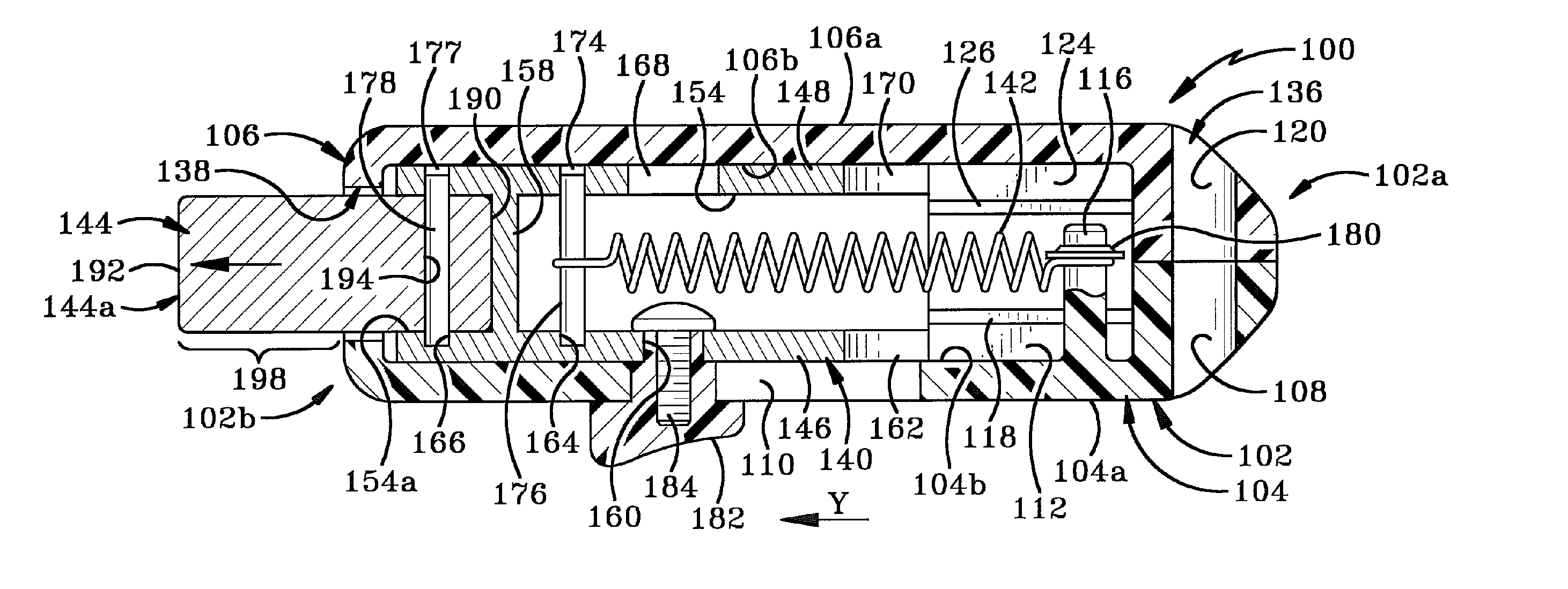
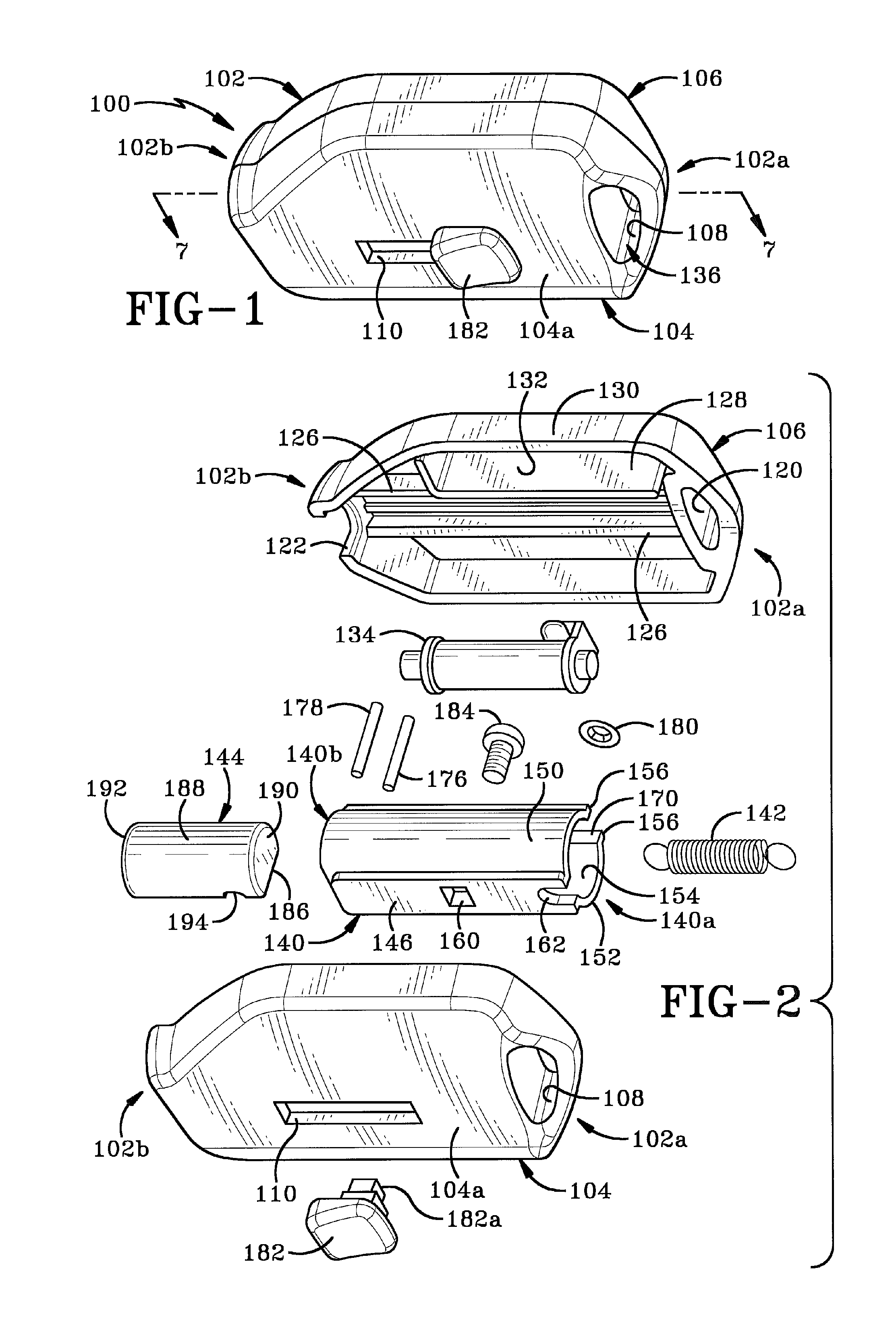
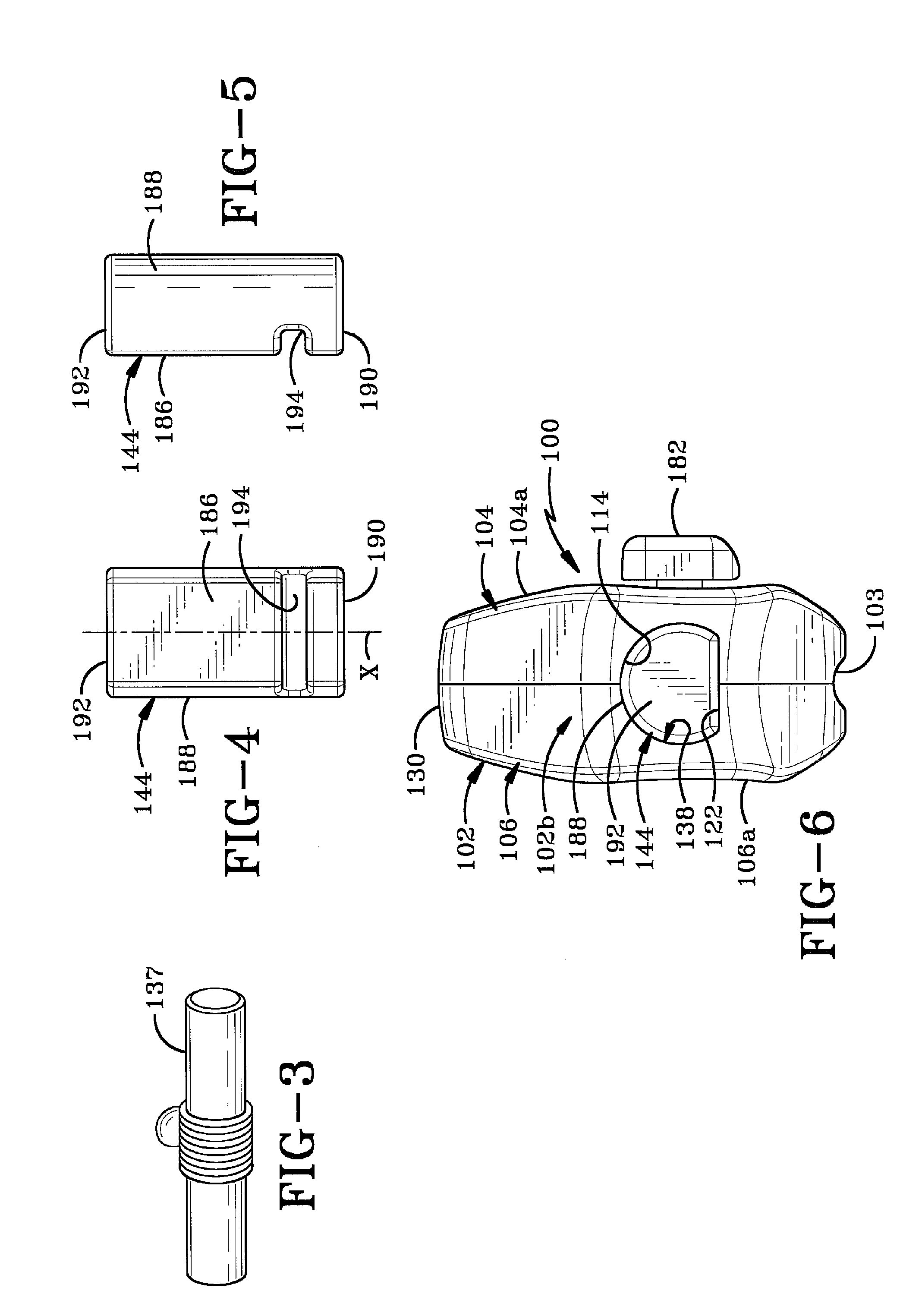
[0025]Referring to FIGS. 1-9, there is shown a magnetic key in accordance with the present invention and generally indicated at 100. Key 100 is adapted to unlock a security device 200 (FIG. 9) which forms part of a display system for items of merchandise (not shown) in order to deter and prevent theft of the items of merchandise.

[0026]In accordance with the present invention, key 100 comprises a housing 102 made up of a first section 104 and a second section 106 that are joined together by ultrasonic welding, an adhesive, etc., to enclose a mechanism for unlocking security device 200. First section 104 of housing 102 comprises a wall having an outer surface 104a and an inner surface 104b. First section 104 defines a first aperture 108 proximate a first end 102a of housing and a longitudinal slot 110 that extends from outer surface 104a through to inner surface 104b. First section 104 also defines an interior chamber 112 within which the unlocking mechanism is partially housed. A fir...


PUM


Abstract

A key for unlocking a magnetically attractable locking mechanism retained within the interior of an anti-theft security device. The key comprises a housing which retains a dipole magnet therein. The dipole magnet is of a specifically designed cross-sectional shape configured to be complementary to a recess in the body of the security device. The shape of the magnet permits it to only enter the recess in one orientation and to bring only the appropriate one of the north or south magnetic poles into the proximity of the locking mechanism. The dipole magnet is movable in the housing between an extended position where at least a portion thereof protrudes from the housing, and a retracted position where the magnet is withdrawn entirely into the housing. The magnet is mounted on a spring-biased slide in the housing that is activated to move the magnet between the extended and retracted positions.

Description

CROSS-REFERENCE TO RELATED CASES[0001]This is a standard utility application claiming priority from U.S. Provisional Application Ser. No. 60 / 879,852, filed Jan. 11, 2007, the entire disclosure of which is incorporated herein by reference.BACKGROUND OF THE INVENTION[0002]1. Technical Field[0003]This invention generally relates to security devices. More particularly, the invention relates to keys for unlocking security devices. Specifically, the invention relates to a magnetic key that includes a dipole magnet for unlocking a magnetically attractable locking mechanism on a security device.[0004]2. Background Information[0005]A variety of security devices are available on the market for deterring theft of items of merchandise. Some of these security devices are attached directly to individual items of merchandise and others are used to secure the systems that display the items of merchandise. A number of these security devices include locks which are unlocked using a magnet.[0006]An ex...

Claims


Application Information

Patent Timeline
IPC IPC(8): E05B47/00
CPCA47F5/0861E05B47/0045E05B47/004E05B19/046Y10T70/7057
Inventor NAGELSKI, KEITH C.
Owner INVUE SECURITY PROD INC
Why Eureka
Try Eureka