
Machine side layer weave design for composite forming fabrics

a technology of composite forming fabrics and machine side layers, applied in the field of woven and composite forming fabrics, can solve the problems of near 2.0 curl test values considered unacceptable, and achieve the effects of less curling, increased weft wear plane, and increased fabric wear resistance and “intensity"

Inactive Publication Date: 2008-07-17
ASTENJOHNSON
View PDF78 Cites 40 Cited by
  • Summary
  • Abstract
  • Description
  • Claims
  • Application Information

AI Technical Summary

Benefits of technology

[0015]In each repeat of the MS weave pattern, each MS weft yarn is interlaced by two adjacent warp yarns so as to form two adjacent MS warp knuckles. In other words, two adjacent warp yarns pass together under each MS weft yarn at each MS weft interlace point. This serves to pull the weft yarn “up” into the interior of the forming fabric causing the MS weft yarn float to bow outwardly, forming an enhanced weft wear plane that is in contact with the fabric bearing surfaces of the papermaking machine on which it is installed. This helps to increase both the wear resistance of the fabric and the “intensity” of crimp imparted to the MS weft. This, in turn, is believed to offset the amount of curl imparted to the fabric by the crimp in the PS weft, thus helping to “pull” the lateral edges of the fabric downward so that it lies flatter and has less curl than that obtained in previous designs.
[0016]The double and single warp knuckles occur throughout and are uniformly distributed over the MS surface of the fabric in groups which include two single knuckles and one double knuckle. The distribution of the warp knuckles is reasonably uniform and does not appear to impart a pronounced twill or herringbone knuckle pattern onto the fabric surface as the warp knuckles are offset from and do not form twill lines. Thus, the MS surface of the novel fabrics is not susceptible to guiding or related tracking issues such as sometimes occur in fabrics where the MS yarn knuckles have a pronounced or clearly discernible angular orientation. Overall, benefits of this novel weave pattern include improved fabric guiding / tracking, good resistance to abrasive weave, and fabric stability.

Problems solved by technology

Curl test values near 2.0 are considered unacceptable and the fabric will require further treatment in order to reduce its edge curl.

Method used


Image

  • Machine side layer weave design for composite forming fabrics
  • Machine side layer weave design for composite forming fabrics
  • Machine side layer weave design for composite forming fabrics

Examples


Embodiment Construction

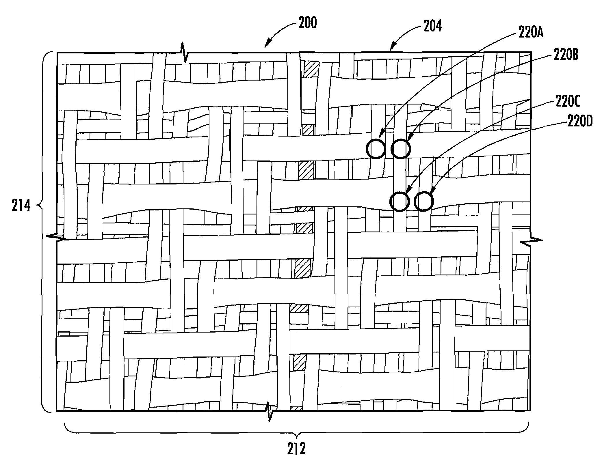
[0041]Certain terminology is used in the following description for convenience only and is not considered limiting. Words such as “up”, “down”, “top”, and “bottom” designate direction in the drawings to which reference is made. This terminology includes the words specifically noted above, derivatives thereof and words of similar input. Additionally, the terms “a” and“one” are defined as including one or more of the referenced data unless specifically noted. The term “crimp” is defined as the bend in the yarns formed by the interweaving of each warp and weft yarn. A “double warp knuckle” is the adjacent knuckle formations caused by a warp yarn passing (or being crimped) under two adjacent weft yarns in the fabric weave structure. A “single warp knuckle” is the knuckle formation caused by a warp yarn passing or being crimped under a single weft yarn, or also refers to each of the adjacent knuckle formations of a double warp knuckle. “Yarns” refers to monofilaments, multi-filaments, tw...


PUM


Abstract

A machine side layer weave design for use in woven composite fabrics, particularly papermakers forming fabrics having differing weave designs on each planar surface is provided. The composite fabric is comprised of two sets of weft yarns interwoven with at least one system of warp yarns. A first set of weft yarns is interwoven with the at least one system of warp yarns to form the paper side layer, while the second set of weft yarns is interwoven with the at least one system of warp yarns to form the machine side layer. In each repeat of the machine side layer weave design, at least 50% of the warp yarns pass under two adjacent weft yarns on the machine side of the fabric to form a double warp knuckle, and each double warp knuckle is bounded on either side by a single warp knuckle formed on each of the first and second weft passed under by the double warp knuckle. Further, in each repeat of the weave, each weft yarn is passed under by two adjacent warp yarns to form two adjacent single warp knuckles. In one embodiment, all of the warp yarns form double warp knuckles; in an alternate embodiment, 50% of the warp yarns form double warp knuckles. The knuckles are evenly distributed across the machine side surface so as to minimize any propensity for guiding. The machine side layer weave design of the invention is suitable for use in any composite fabric and is effective in minimizing or eliminating fabric edge curl, a problem common in fabrics of this type.

Description

CROSS-REFERENCE TO RELATED APPLICATION[0001]This application claims the benefit of U.S. Provisional Application No. 60 / 869,144, filed Dec. 8, 2006, which is incorporated herein by reference as if fully set forth.FIELD OF THE INVENTION[0002]The present invention is directed to woven, composite forming fabrics for use in papermaking machines. It is particularly concerned with such fabrics wherein the machine side fabric weave helps to reduce edge curl.BACKGROUND[0003]Composite forming fabrics, such as those described in U.S. Pat. No. 5,826,627 (Seabrook et al.), WO 06 / 034576 (Danby et al) or U.S. Pat. No. 7,108,020 (Stone) are comprised of two sets of weft yarns interwoven with at least one system of warp yarns. One of the sets of weft yarns is located on the paper side surface (PS) of the fabric to provide support for the papermaking fibers in the sheet forming process; these weft yarns tend to be small and closely woven, typically in a plain weave or 3-shed pattern so as to maximize...

Claims


Application Information

Patent Timeline
Patent Type & Authority Applications(United States)
IPC IPC(8): D03D11/00D21F1/38
CPCD03D13/00D21F1/0036D03D13/004
Inventor BARRETT, REX
Owner ASTENJOHNSON
Features
  • Generate Ideas
  • Intellectual Property
  • Life Sciences
  • Materials
  • Tech Scout
  • Unparalleled Data Quality
  • Higher Quality Content
  • 60% Fewer Hallucinations
Learn More