Bracket for mounting a utility meter transponder

a technology for meter boxes and brackets, which is applied in the field of brackets, can solve the problems of damage to difficulty in communicating with the wireless network of the utility meter transponder, and prior art does not teach a bracket that is attached to the meter box and adapted to mount the transponder, etc., and achieves the effect of convenient installation and low manufacturing cos

Inactive Publication Date: 2008-07-17
MCCLURE RANDY K +1
View PDF7 Cites 17 Cited by
  • Summary
  • Abstract
  • Description
  • Claims
  • Application Information

AI Technical Summary

Benefits of technology

[0016]Another objective is to provide a mounting bracket that is inexpensive to manufacture and easy to install.

Problems solved by technology

If the utility meter transponder is simply placed underground next to the utility meter, however, it may be difficult for the utility meter transponder to communicate with the wireless network.
Also, utility, bugs, and other environmental factors may damage the utility meter transponder if it is left resting on the ground.
However, the prior art does not teach a bracket that is attached to the meter box and adapted to mount the transponder.

Method used


Image

  • Bracket for mounting a utility meter transponder
  • Bracket for mounting a utility meter transponder
  • Bracket for mounting a utility meter transponder

Examples


first embodiment

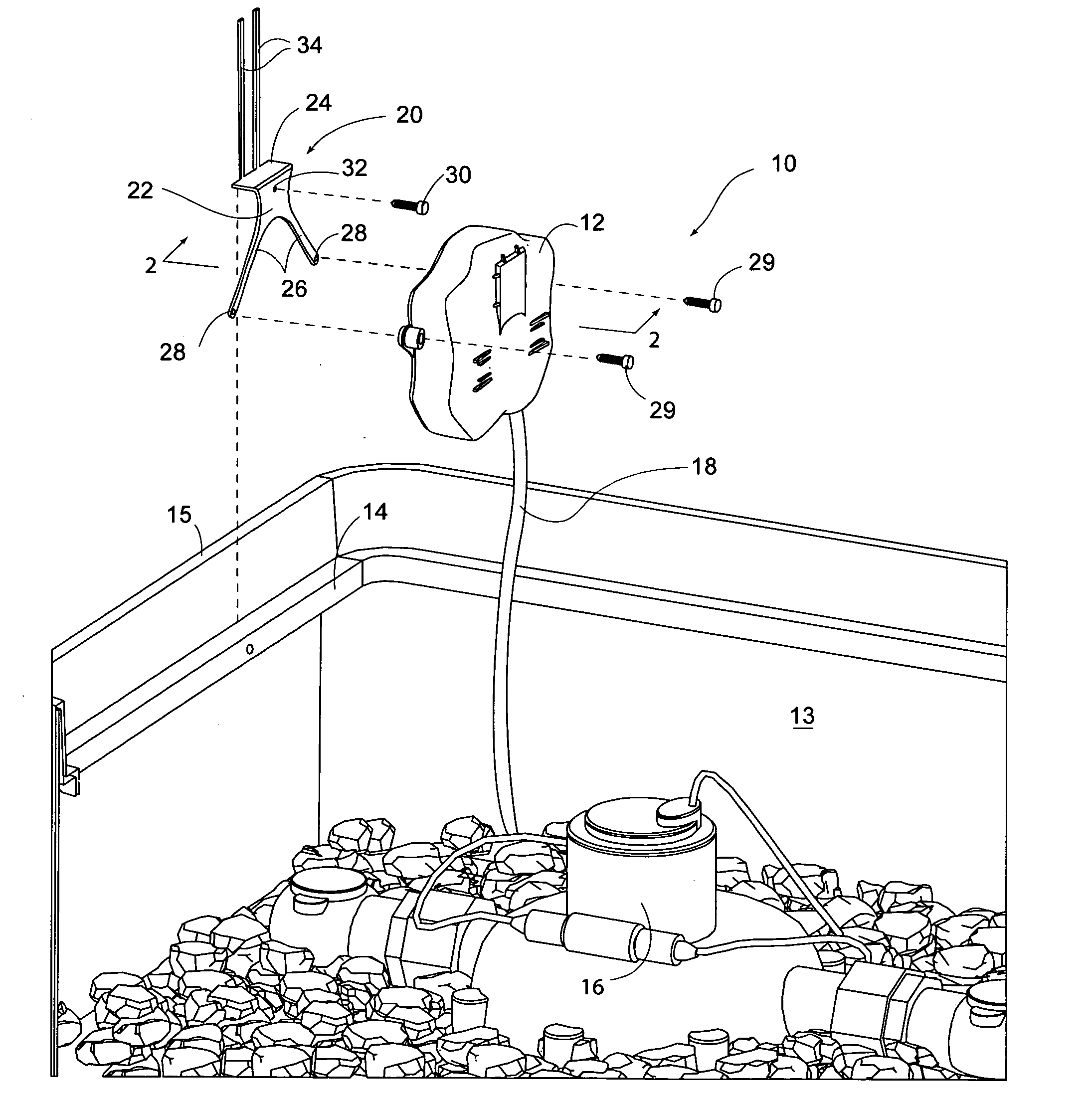
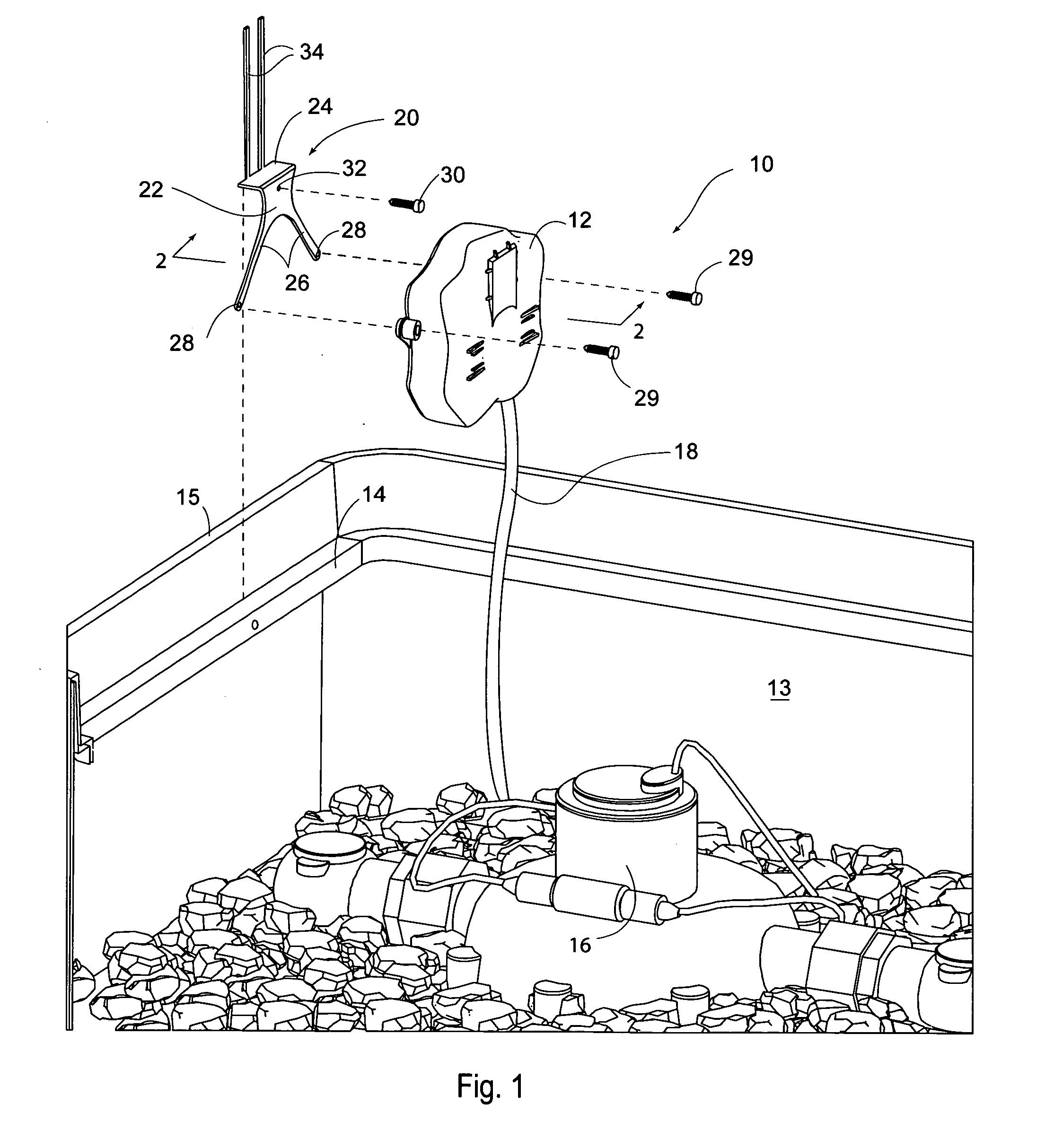
[0028]FIG. 1 is an exploded perspective view of the transponder system 10 including the utility meter transponder 12, and a mounting bracket 20 for mounting the utility meter transponder 12 to the meter box 13. FIG. 2 is a sectional view thereof taken along line 2-2 in FIG. 1. As shown in FIGS. 1 and 2, the mounting bracket 20 includes a base element 22 adapted to abut the meter box 13, and a mounting flange 24 extending outwardly from the base element 22. The mounting flange 24 is adapted to engage and rest upon the lip 14 of the meter box 13.

[0029]For purposes of this application, the term lip 14 shall be expressly defined to include the perimeter 15 of the meter box 13, which is structurally equivalent to the lip 14. The mounting bracket 20 further includes a transponder mounting element 26 extending downwardly from the base element 22 opposite the mounting flange 24. The transponder mounting element 26 is adapted to mount the utility meter transponder 12 on the mounting bracket ...

second embodiment

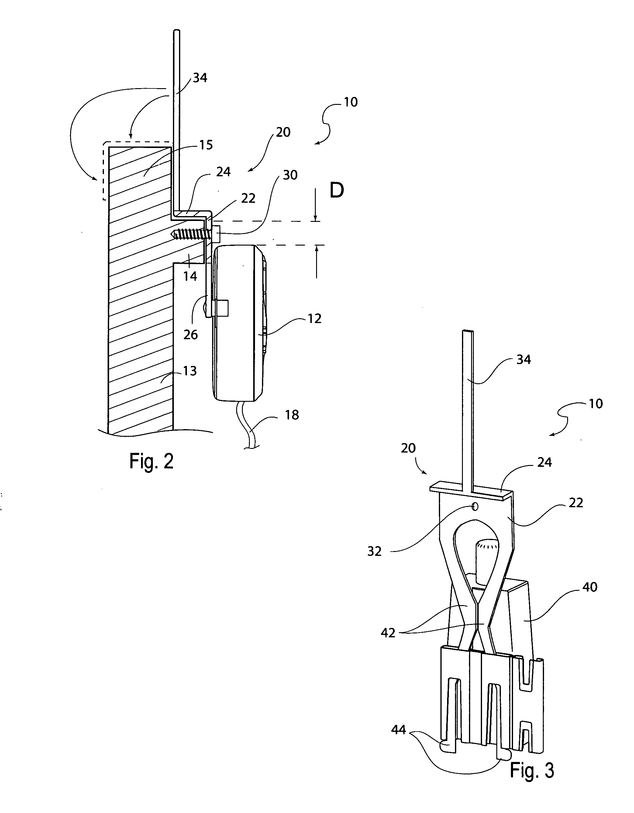
[0036]FIG. 3 is rear perspective view of the transponder system 10. In this embodiment, the transponder mounting element includes two downwardly extending legs 42 that biased towards a locking position, as shown in FIG. 3, but can flex to an unlocking position for receiving and lockingly engaging an alternative embodiment of a utility transponder 40. In the most preferred embodiment, each of the downwardly extending legs 42 includes a locking tab 44 that extends outwardly from the leg 42 for locking the utility transponder 40 on the mounting bracket 20 and for preventing it from being knocked off.

third embodiment

[0037]FIG. 4 is front perspective view of the transponder system 10. In this embodiment, the transponder mounting element of the mounting bracket 20 is an aperture 52 adapted to receive the utility meter transponder 50. Once this embodiment of the mounting bracket 20 has been installed by mounting the mounting flange 24 on the lip 14, as previously discussed, the utility meter transponder 50 is inserted into the aperture 52 and physically supported by the mounting bracket 20.


PUM


Abstract

A mounting bracket for mounting a utility meter transponder on a lip of a meter box has a base element adapted to abut the meter box, and a mounting flange extending outwardly from the base element to engage the lip of the meter box. A fastener is adapted to fasten the base element to the meter box; and a transponder mounting element extending downwardly from the base element opposite the mounting flange. The transponder mounting element is adapted to mount the utility meter transponder.

Description

CROSS-REFERENCE TO RELATED APPLICATIONS[0001]Not ApplicableSTATEMENT REGARDING FEDERALLY SPONSORED RESEARCH[0002]Not ApplicableBACKGROUND OF THE INVENTION[0003]1. Field of the Invention[0004]This invention relates generally to brackets, and more particularly to a mounting bracket for mounting a utility meter transponder adjacent a lip of a meter box.[0005]2. Description of Related Art[0006]To facilitate reading utility meters, many cities are installing utility meter transponders adjacent the utility meter to enable wireless reporting of utility meters via the utility meter transponder. If the utility meter transponder is simply placed underground next to the utility meter, however, it may be difficult for the utility meter transponder to communicate with the wireless network. Also, utility, bugs, and other environmental factors may damage the utility meter transponder if it is left resting on the ground. To ensure that the utility meter transponders are mounted above the ground and...

Claims


Application Information

Patent Timeline
Patent Type & Authority Applications(United States)
IPC IPC(8): F16L3/00
CPCG01D4/002G01D11/30G01F15/063Y04S20/50Y02B90/241Y02B90/247Y04S20/32H02G9/10Y02B90/20Y04S20/30
Inventor MCCLURE, RANDY K.CARVALHO, ELAINE
Owner MCCLURE RANDY K
Why Eureka
Try Eureka