Rechargeable battery

a rechargeable battery technology, applied in the field of rechargeable batteries, can solve the problems of increased voltage, lithium-ion batteries may be exposed to a danger of explosion, and the housing must be suitable, so as to achieve the effect of improving the rechargeable battery

Active Publication Date: 2008-07-17
SAMSUNG SDI CO LTD
View PDF5 Cites 37 Cited by
  • Summary
  • Abstract
  • Description
  • Claims
  • Application Information

AI Technical Summary

Benefits of technology

[0018]It is therefore an object of the present invention to provide an improved rechargeable battery.

Problems solved by technology

Meanwhile, the Lithium-ion battery may be exposed to a danger of explosion by a sudden increase of the voltage in the cases of an external short-circuit, an internal short-circuit by a mechanical impact, or an over-charge / over-discharge.
The housing of the battery has a problem, however, that the housing must be produced suitable for the shape and the structure of the external device.
On the other hand, for the inner pack battery, because an extra decoration case is attached when the inner pack battery is mounted on the external device, the loading process of the inner pack battery is troublesome compared to that of the hard pack battery.
Accordingly, the longitudinal size of the battery is increased, reducing the capacity per volume of the battery.
Therefore, the battery may be easily twisted or bent by an external force.
That is, if the molding resin part is twisted about the bare cell beyond a certain angle, the electrical connection between the anode terminal or the cathode terminal of the bare cell and the external terminal of the protective circuit board through the lead plate may be unstable, even when the molding resin part is not completely broken.
In addition, the safety devices of the battery may not to operate normally,
In addition, the method of combining the molding resin part by the melting method has a problem that the manufacturing process is complicated and the cost is high.
Therefore, the productivity becomes low.

Method used


Image

  • Rechargeable battery
  • Rechargeable battery
  • Rechargeable battery

Examples


case 400

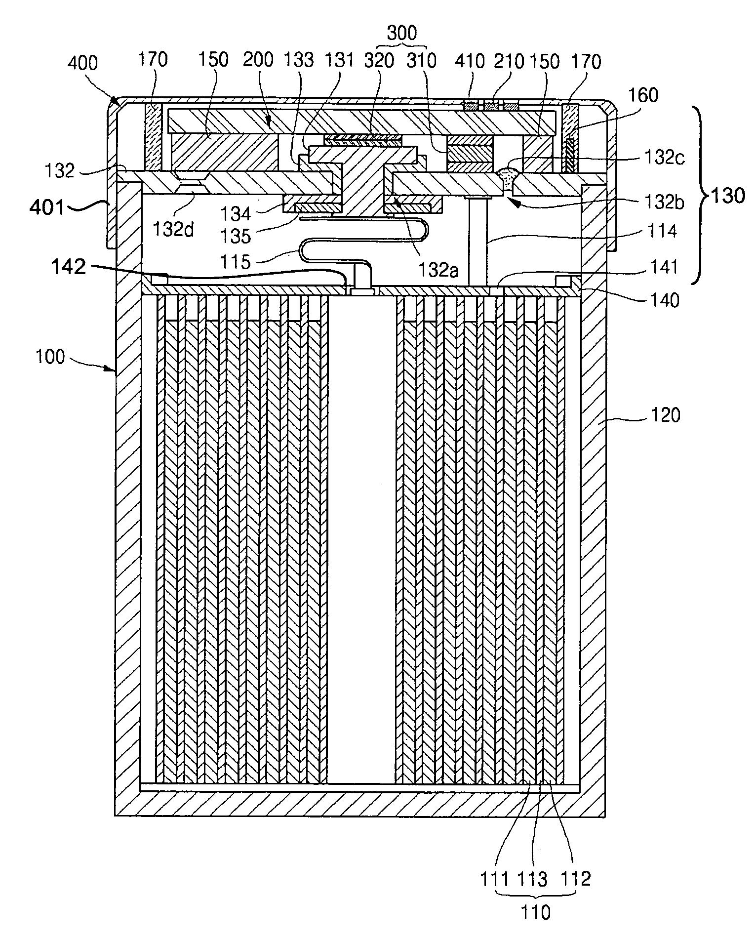
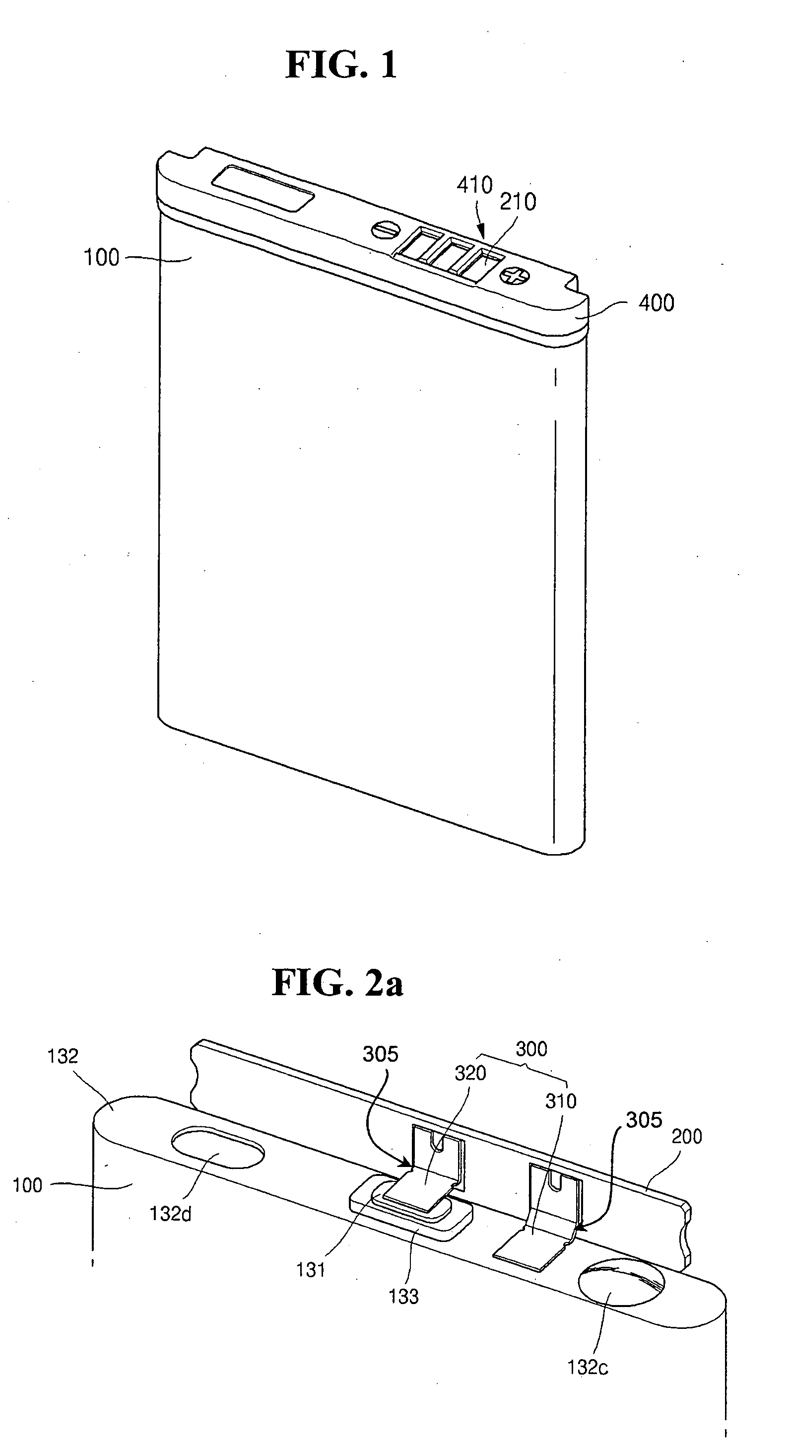
[0070]Combining case 400 is constructed with an injection molded case that has a space formed inside so as to cover protective circuit board 200 when connected to bare cell 100. Combining case 400 has a sleeve surface 401 at the inside lower part of combining case. When combining case 400 is connected to bare cell 100, sleeve surface 401 is connected to bare cell 100 in a sleeve method surrounding the upper end circumference of bare cell 100. The sleeve method installs sleeve surface 401 of combining case 400 to surround the circumference of the upper end surface of bare cell 100. Accordingly, the upper end of bare cell 100 is overlapped by bare cell 100 and combining case 400, thereby improving safety.

[0071]On the other hand, combining case 400 can be prevented from being easily separated from the upper end of bare cell 100 by enhancing the adhesive force between combining case 400 and bare cell 100. Particularly, it is possible to enhance the adhesive force between combining case ...


PUM

PropertyMeasurementUnit
voltageaaaaaaaaaa
shapeaaaaaaaaaa
positive temperature coefficientaaaaaaaaaa

Abstract

A rechargeable battery. The rechargeable battery is constructed with a bare cell, a protective circuit board electrically connected to the bare cell, a lead plate located between the bare cell and the protective circuit board, and a combining case covering an upper end of the bare cell, the protective circuit board and the lead plate. The lead plate is constructed with a first plate electrically connected to the protective circuit board, a second plate electrically connected to the bare cell, and an inside bending part connected between the first plate and the second plate. The first plate of the lead plate is bent around the inside bending part at 180 degrees such that the bare cell is coupled with the protective circuit board in parallel. Therefore, a distance between the bare cell and the protective circuit is reduced, and the capacity per volume of the rechargeable battery is increased.

Description

CLAIM OF PRIORITY[0001]This application makes reference to, incorporates the same herein, and claims all benefits accruing under 35 U.S.C. §119 from an application for RECHARGEABLE BATTERY earlier filed in the Korean Intellectual Property Office on 17 Jan. 2007 and there duly assigned Serial No. 10-2007-0005431.BACKGROUND OF THE INVENTION[0002]1. Field of the Invention[0003]The present invention relates to a rechargeable battery, and more particularly, to a rechargeable battery that can simplify a manufacturing process and improve the capacity, compared with a conventional rechargeable battery.[0004]2. Description of the Related Art[0005]Generally, a rechargeable battery can be used repeatedly if the rechargeable battery is charged, unlike a disposable battery. The rechargeable battery has been used mainly as a power source for electronic device used for communication, for information processing, and for multimedia. Since a rechargeable battery is a power source having ultra-light w...

Claims


Application Information

Patent Timeline
Patent Type & Authority Applications(United States)
IPC IPC(8): H01M2/02H01M14/00
CPCH01M2/22H01M2200/106H01M10/425H01M10/42H01M50/528Y02E60/10Y02P70/50
Inventor SEO, KYUNGWONBYUN, JEONGDEOKKWON, YONGGEOLKOH, SEOK
Owner SAMSUNG SDI CO LTD
Why Eureka
Try Eureka