
Method of improving channel switching speed in digital television receiver and the digital television receiver

a technology of digital television receiver and channel switching speed, which is applied in the direction of television signal transmission, two-way working system, pulse modulation, etc., can solve the problem of longer time consumed to switch a broadcasting channel than that consumed in an analog tv receiver, and achieve the effect of rapid completion of channel switching

Inactive Publication Date: 2008-07-17
SAMSUNG ELECTRONICS CO LTD
View PDF9 Cites 5 Cited by
  • Summary
  • Abstract
  • Description
  • Claims
  • Application Information

AI Technical Summary

Benefits of technology

The present invention provides a method and apparatus for quickly switching channels in a digital broadcasting receiver. This is useful when there are errors in the transport stream, as it allows for faster demultiplexing and decoding of the video and audio data. The method includes starting screen mute when a channel change is initiated, generating transport stream packets, and reproducing the video and audio data. The screen mute is only ended when a normal image display is possible. The technical effect of this invention is to improve the user experience when switching channels in a digital broadcasting receiver.

Problems solved by technology

However, when the digital TV receiver is used, there is a problem in that time consumed to switch a broadcasting channel is longer than that consumed in an analog TV receiver.

Method used


Image

  • Method of improving channel switching speed in digital television receiver and the digital television receiver
  • Method of improving channel switching speed in digital television receiver and the digital television receiver
  • Method of improving channel switching speed in digital television receiver and the digital television receiver

Examples


Embodiment Construction

[0027]Hereinafter, exemplary embodiments of the present invention will be described in detail with reference to the attached drawings.

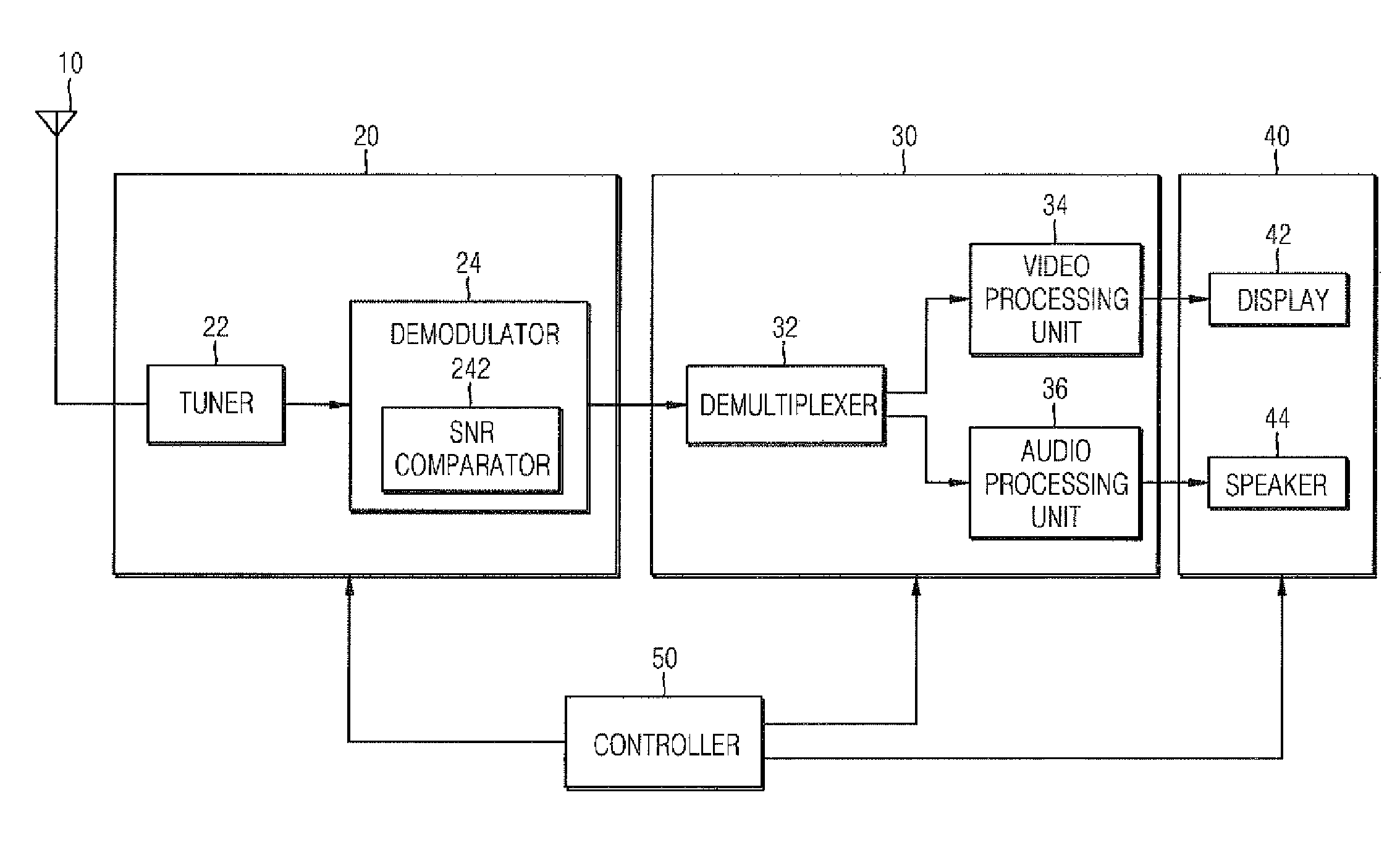
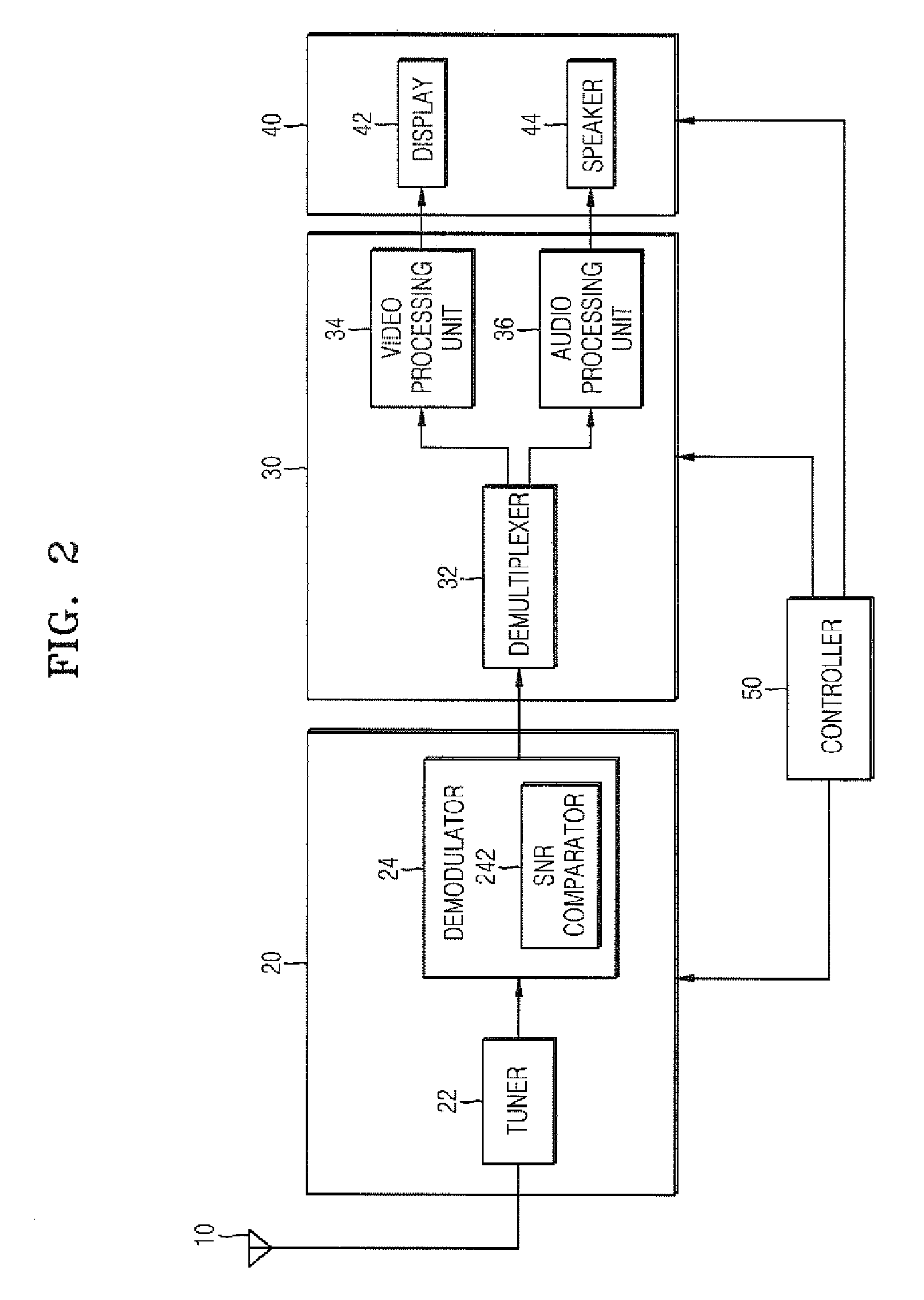
[0028]FIG. 2 is a block diagram showing a digital television (TV) receiver in which a method of improving a channel switching speed is implemented according to an embodiment of the present invention. Referring to FIG. 2, the digital TV receiver includes an antenna 10, a tuning and demodulating unit 20, a data processing unit 30, and a reproducing unit 40, which are connected in a listed order.

[0029]The tuning and demodulating unit 20 generates transport stream packets by tuning and demodulating a broadcasting signal of a broadcasting channel selected by a channel change instruction and outputs the transport stream packets to the data processing unit 30 even when the transport stream packets have errors therein. The tuning and demodulating unit 20 includes a tuner 22 and a demodulator 24. The tuner 22 performs a tuning operation on the broadcasting cha...


PUM


Abstract

Provided is a method of improving a channel switching speed in a digital television (TV) receiver. The method includes: generating transport stream packets by channel tuning and demodulating a broadcasting signal of a channel selected by the channel change instruction;outputting the transport stream packets before completion of tuning and demodulating of the broadcast signal; andgenerating video and / or audio data by demultiplexing and decoding the outputted transport stream packets. In addition, a digital TV receiver applying the improvement of the channel switching speed is provided. The digital TV receiver includes a tuning and demodulating unit generating transport stream packets by tuning and demodulating a broadcasting signal of a broadcasting channel selected by a channel change instruction and outputting the transport stream packets before completion of the tuning and demodulation of the transport stream packets. The digital TV receiver starts screen mute in response to the channel change instruction and terminates the screen mute when a normal image display is possible by using the transport stream packets output from the tuning and demodulating unit. Therefore, the channel switching speed increases as compared with a case where the improvement of the channel switching speed is attempted by using the transport stream packets.

Description

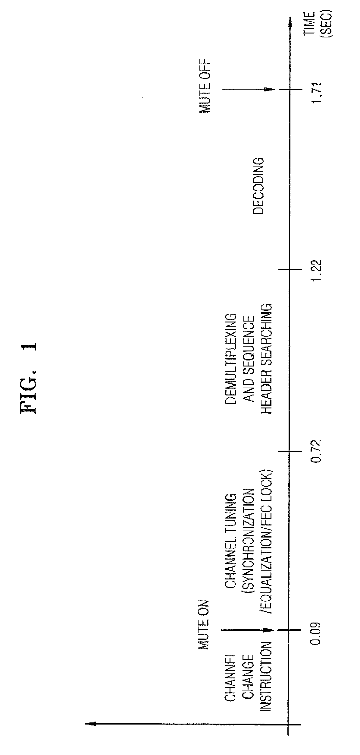
CROSS-REFERENCE TO RELATED PATENT APPLICATION[0001]This application claims the benefit of Korean Patent Application No. 10-2007-0003974, filed on Jan. 12, 2007, in the Korean Intellectual Property Office, the disclosure of which is incorporated herein in its entirety by reference.BACKGROUND OF THE INVENTION[0002]1. Field of the Invention[0003]The present invention relates to channel switching in a digital television (TV) receiver, and more particularly, to a method of improving a broadcasting channel switching speed in a digital TV receiver and the digital TV receiver for improving the broadcasting channel switching speed.[0004]2. Description of the Related Art[0005]Recently, as digital television (TV) broadcasting has been actively developed, users of digital TV receivers continuously increase. However, when the digital TV receiver is used, there is a problem in that time consumed to switch a broadcasting channel is longer than that consumed in an analog TV receiver.[0006]FIG. 1 sh...

Claims


Application Information

Patent Timeline
Patent Type & Authority Applications(United States)
IPC IPC(8): H04N7/24
CPCH04N21/2368H04N21/4341H04N21/8106H04N21/472H04N21/4384H04N5/44
Inventor KANG, HEE-BEOMCHUN, KANG-WOOKJUNG, CHOON-SIK
Owner SAMSUNG ELECTRONICS CO LTD
Learn More