
Air compressor

a compressor and air technology, applied in the direction of pump components, positive displacement liquid engines, liquid fuel engine components, etc., can solve the problems of reducing the storage quantity of compressed air, generating a loud noise, and taking a long time to fully discharge condensate and compressed air, so as to achieve the effect of further reducing the noise generated by compressed air

Active Publication Date: 2019-09-19
MAKITA CORP
View PDF0 Cites 2 Cited by
  • Summary
  • Abstract
  • Description
  • Claims
  • Application Information

AI Technical Summary

Benefits of technology

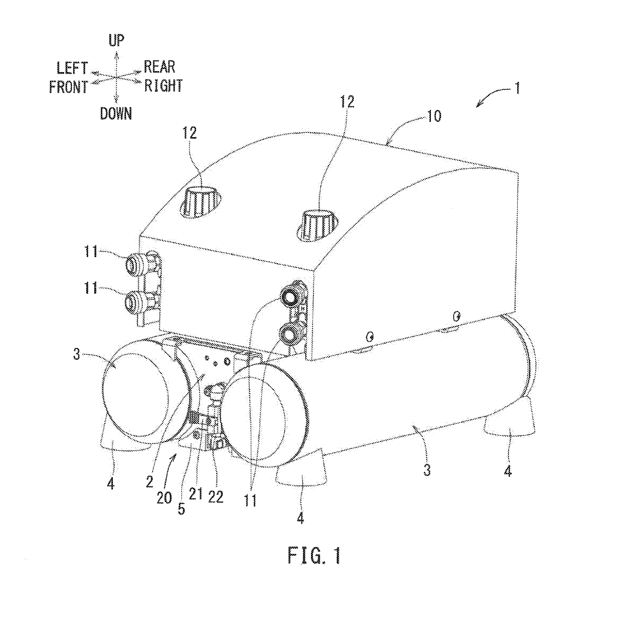
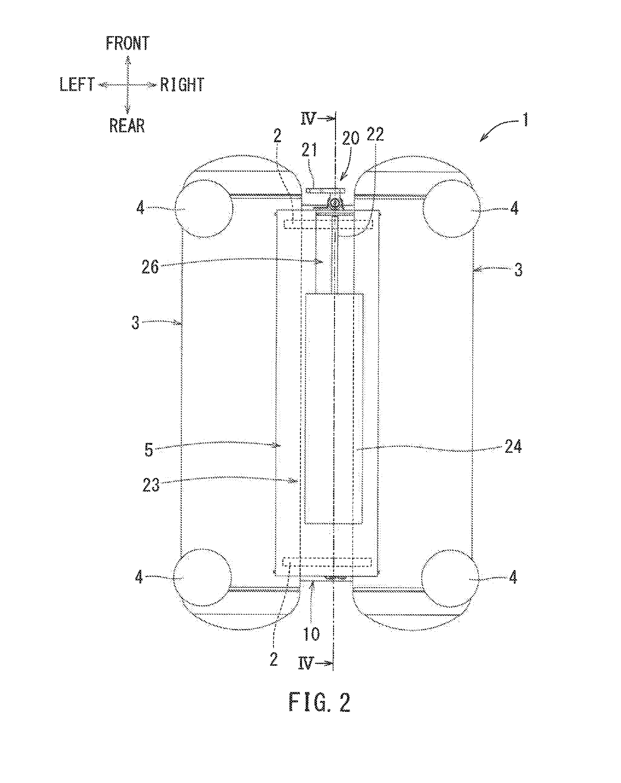
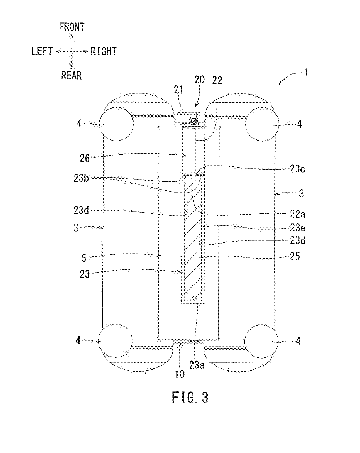
The invention is about an improved design for an air compressor that reduces noise and prevents the scattering of condensate around the compressor. The design is achieved through the use of a wool-like fiber material that has high permeability and low water absorbency, which allows the compressed air and condensate to flow without being retained in the fiber material. This results in efficient discharging without the need for adjusting the amount of air released. Additionally, the air compressor design allows for noise reduction through the use of a muffling chamber and the effective utilization of empty space between two tanks to create a compact air compressor.

Problems solved by technology

The condensate accumulated in the tank can cause rust to develop within the tank and result in a decrease in the storage quantity of the compressed air.
This may generate a loud noise.
However, when the degree of opening of the drain cock is reduced to a small degree, it takes a long time to fully discharge the condensate and the compressed air, and possibly inconvenience a user.
However, when the muffling material is used, clogging may occur due to the condensate that is discharged together with the compressed air.
This can result in deterioration of discharge performance.
Due to the dispersion of the compressed air, the energy that the compressed air possesses will be consumed.
Furthermore, the muffling chamber can restrict the movement of the wool-like fiber member.

Method used


Image

  • Air compressor
  • Air compressor
  • Air compressor

Examples


Embodiment Construction

[0029]The detailed description set forth below, when considered with the appended drawings, is intended to be a description of exemplary embodiments of the present invention and is not intended to be restrictive and / or to represent the only embodiments in which the present invention can be practiced. The term “exemplary” used throughout this description means “serving as an example, instance, or illustration,” and should not necessarily be construed as preferred or advantageous over other exemplary embodiments. The detailed description includes specific details for the purpose of providing a thorough understanding of the exemplary embodiments of the invention, it will be apparent to those skilled in the art that the exemplary embodiments of the invention may be practiced without these specific details. In some instances, these specific details refer to well-known structures, components and / or devices that are shown in block diagram form in order to avoid obscuring significant aspect...


PUM


Abstract

A wool-like fiber member that has high permeability and low absorbability is disposed around a discharge port of a discharge pipe that is configured to discharge condensate and compressed air stored within a tank.

Description

CROSS-REFERENCE[0001]This application claims priority to Japanese patent application serial number 2018-047666, filed on Mar. 15, 2018, the contents of which are incorporated herein by reference in their entirety.TECHNICAL FIELD[0002]The present invention generally relates to the field of air compressors that generate and store compressed air.BACKGROUND ART[0003]Generally, an air compressor takes in outside air and brings it to the inside of a cylinder and compresses it using a piston to generate compressed air inside the cylinder. The compressed air thus generated is delivered to a storage tank to be stored.[0004]The compressed air stored in the tank is supplied to an air-powered tool such as, for example, a nail driver for the operation. As the compressed air is supplied to the tool, in other words, to the outside of the storage tank, the remaining compressed air in the storage tank will expand. As a result, the compressed air will be cooled. Due to this cooling effect, water vapo...

Claims


Application Information

Patent Timeline
Patent Type & Authority Applications(United States)
IPC IPC(8): F04B53/00F04B53/20
CPCF04B53/20F04B53/004F04B41/02F04B39/16F04B39/0061F04B39/005
Inventor HACHISUKA, TOMOHIRO
Owner MAKITA CORP
Learn More