
Bottom wear

Inactive Publication Date: 2021-11-25
TORAY IND INC
View PDF0 Cites 3 Cited by
  • Summary
  • Abstract
  • Description
  • Claims
  • Application Information

AI Technical Summary

Benefits of technology

The patent text describes a bottom wear that can be used with protective bands for lumbago. This bottom wear has a cylindrical part on the back of a waist-encircling section where the protective band can be attached. This makes it easy for workers to quickly and easily attach the protective band to their work trousers. This bottom wear is designed to tighten the waist of the wearer and provide support during work activities.

Problems solved by technology

However, according to the findings by the inventors, a bottom wear in which protections for lumbago can be integrally attached as disclosed in Patent Document 1 has a structure in which when a protection band for lumbago (hereinafter, sometimes referred to simply as a “band”) is attached to a cylindrical part, the protection band for lumbago is inserted through an opening disposed at one of both ends of the cylindrical part, and the work for insertion of the protection band for lumbago tends to be work taking much time and a lot of energy due to occurrence of troubles such that an end of protection band for lumbago or the like is caught on a lateral surface inside the cylindrical part in the middle, so that the protection band for lumbago is stuck inside the cylindrical part.
Further, occupational workers who have a high risk of being attacked by the low back pain, such as workers relating to transportation business, medical workers, and workers relating to services in social welfare facilities for care of the elderly and the like, often perform the work for insertion of the protection band for lumbago in limited dressing space.
In addition, since mostly a plurality of persons change clothes at the same time, it is difficult to secure enough space for one person, and the persons try to change clothes quickly in order to provide dressing space for other persons.
However, even when a hand is inserted through the other opening of the cylindrical part to pull out the band as mentioned above, it is difficult to insert the hand to a position at which the band is stuck if the distance over which the band passes (hereinafter, sometimes referred to as a “band passage distance”), such as a distance from one opening to the other opening of the cylindrical part.
Due to the above-mentioned problems, the bottom wear disclosed in Patent Document 1, which cannot choose but employ a method in which a band is inserted through an opening disposed at one of both ends of the cylindrical part, has the problem that it takes much time for the wearer to complete attachment of the protection band for lumbago to the cylindrical part.

Method used


Image

  • Bottom wear
  • Bottom wear
  • Bottom wear

Examples


example 1

[0163]Polyethylene terephthalate yarns of 167 dtex and spun yarns with 65% of polyester and 35% (mass ratio) of cotton were used as warp threads, and polyethylene terephthalate yarns of 167 dtex were used as weft threads to weave a warp double twill fabric at a warp density of 154 threads / 2.54 cm and a weft density of 64 threads / 2.54 cm, thereby obtaining a cloth A for cloth of bottom wear with 90% of polyester and 10% of cotton.

[0164]Subsequently, nylon yarns of 78 dtex and polyurethane elastic fiber of 310 dtex were used to knit a fabric, thereby obtaining a power net cloth with 82% of nylon and 18% of polyurethane (hereinafter, the power net cloth is referred to as a “cloth D”).

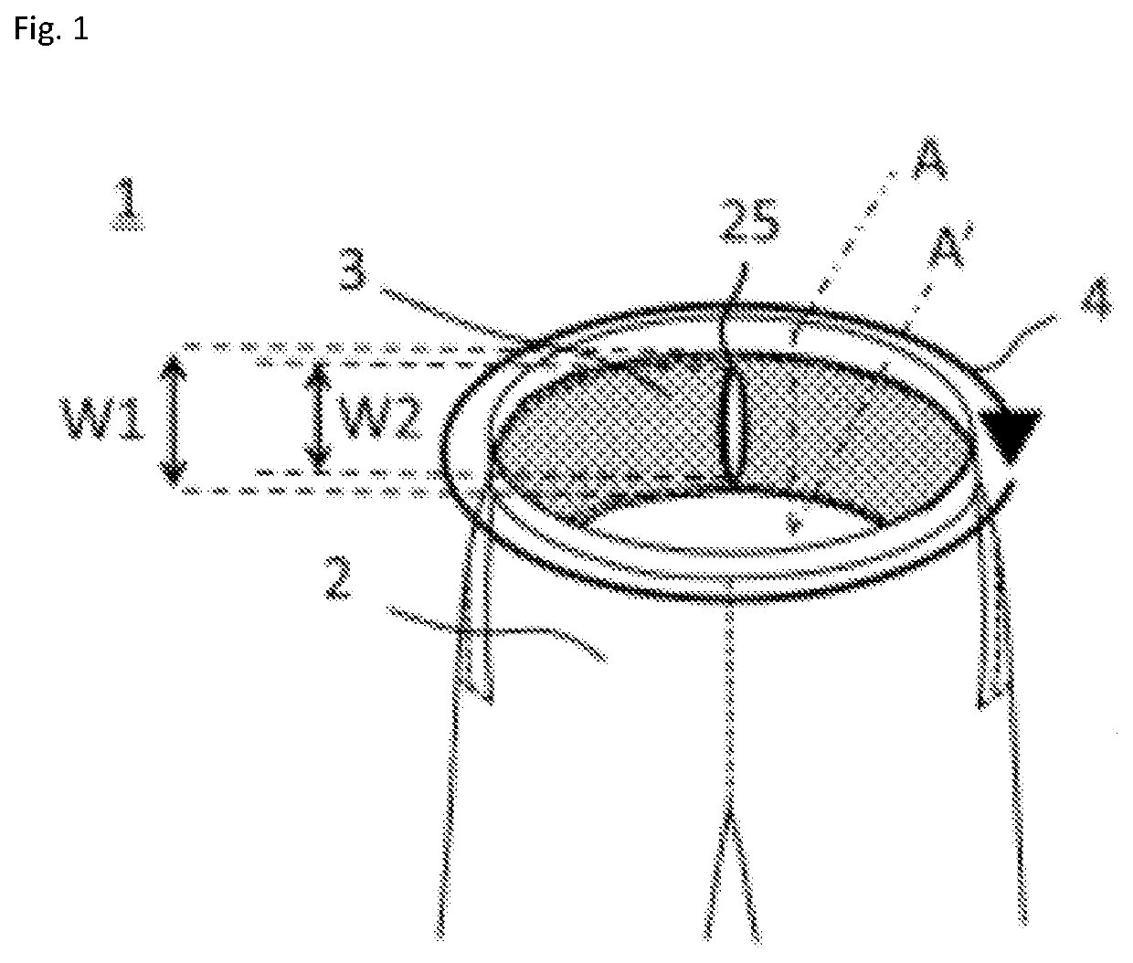
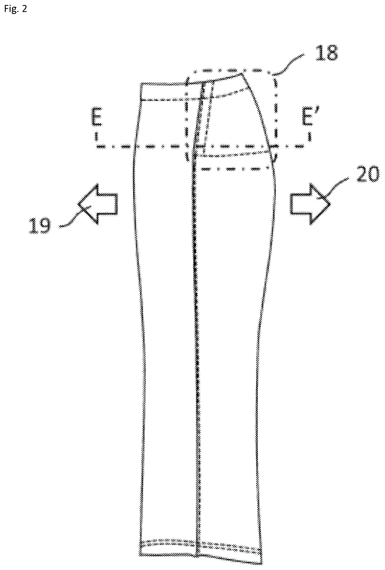
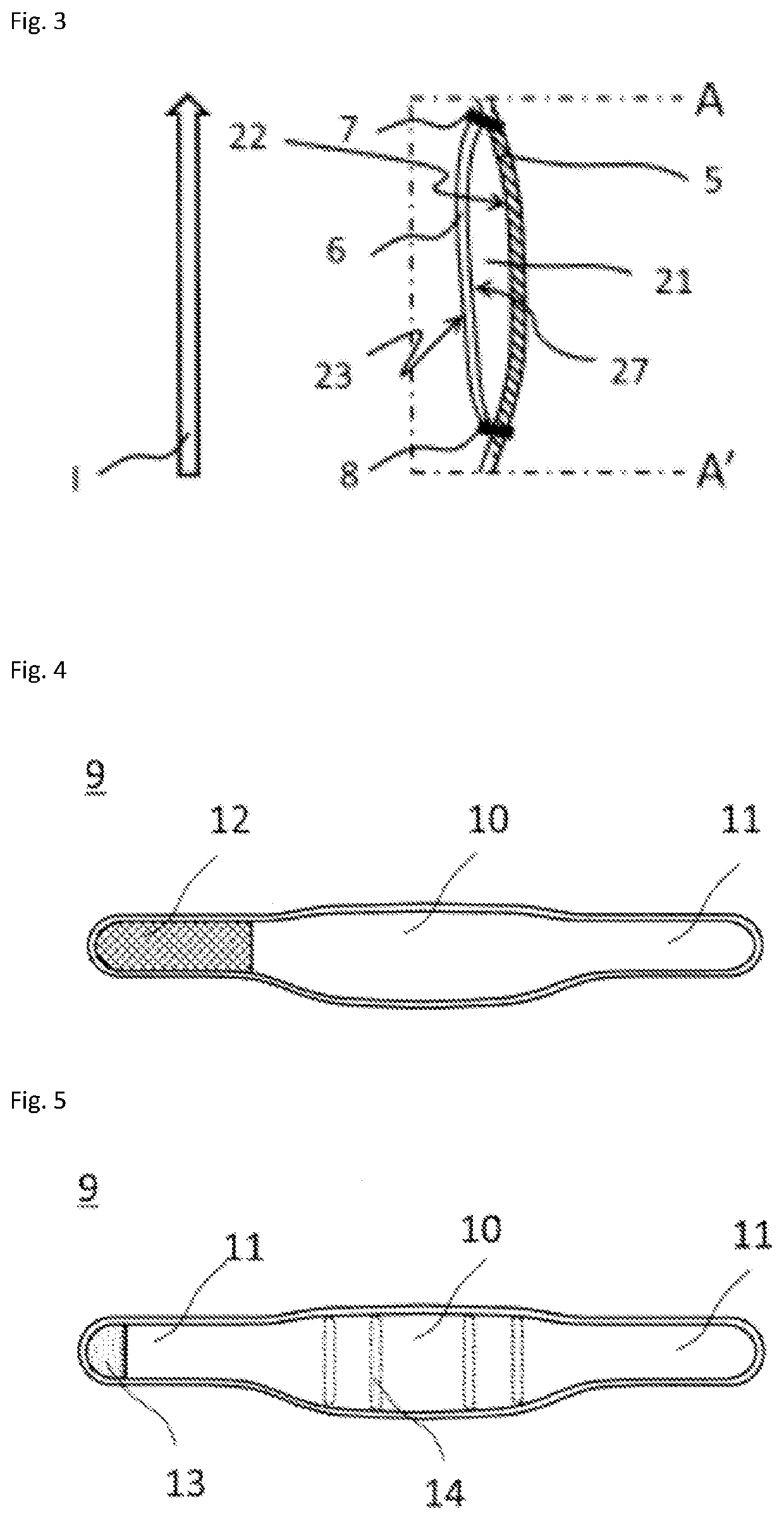
[0165]The cloth A for cloth of bottom wear bottom was used as a cloth of bottom wear to prepare a bottom wear having an appearance as shown in FIGS. 1 and 2 and an inner part as shown in FIG. 3. That is, the fabric of the cylindrical part rear portion in FIG. 3 is a bottom wear cloth on the back portion in...

example 2

[0166]A cloth of bottom wear was prepared using the same cloth A as used in Example 1, and further, the same cloth D as used in Example 1 was used to prepare a cylindrical part, thereby preparing a bottom wear having an appearance as shown in FIGS. 1 and 2 and an inner part as shown in FIG. 3. That is, the fabric of the cylindrical part rear portion in FIG. 3 is a bottom wear cloth on the back portion in the waist-encircling section of the cloth of bottom wear formed of the cloth A, and the fabric of the cylindrical part front portion (planar material) is the cloth D. In addition, one slit as shown in FIG. 1 was provided at the central part of the cylindrical part front portion, a cylindrical part was prepared in such a manner that the ratio (W2 / W1) of the width of the slit in the longitudinal direction (W2) to the width of the cylindrical part (W1) was 0.94. The protection band for lumbago 1 having a configuration as shown in FIGS. 4 and 5 was attached to the cylindrical part of th...

example 3

[0167]A cloth of bottom wear was prepared using the same cloth A as used in Example 1, and further, the same cloth D as used in Example 1 was used to prepare a cylindrical part, thereby preparing a bottom wear having an appearance as shown in FIGS. 1 and 2 and an inner part as shown in FIG. 3. That is, the fabric of the cylindrical part rear portion in FIG. 3 is a bottom wear cloth on the back portion in the waist-encircling section of the cloth of bottom wear formed of the cloth A, and the fabric of the cylindrical part front portion (planar material) is the cloth D. In addition, one slit as shown in FIG. 1 was provided at the central part of the cylindrical part front portion, a cylindrical part was prepared in such a manner that the ratio (W2 / W1) of the width of the slit in the longitudinal direction (W2) to the width of the cylindrical part (W1) was 0.75. The protection band for lumbago 1 having a configuration as shown in FIGS. 4 and 5 was attached to the cylindrical part of th...


PUM


Abstract

A bottom wear is described which has a cylindrical part on the back part of a waist-encircling section and inside the bottom wear and in which a protection band for lumbago can be attached to a bottom wear such as work trousers suitable for use with a protection band for lumbago for tightening a waist of a wearer. The bottom wear allows the wearer to quickly complete work for attaching the protection band for lumbago to the cylindrical part. One slit is present at the substantially central part of the front portion of the cylindrical part, wherein the slit is disposed in such a manner that the longitudinal direction is substantially parallel to the wearer's stature direction.

Description

CROSS REFERENCE TO RELATED APPLICATIONS[0001]This is the U.S. National Phase application of PCT / JP2019 / 036329, filed Sep. 17, 2019, which claims priority to Japanese Patent Application No. 2018-178710, filed Sep. 25, 2018, the disclosures of these applications being incorporated herein by reference in their entireties for all purposes.FIELD OF THE INVENTION[0002]The present invention relates to a bottom wear.BACKGROUND OF THE INVENTION[0003]Among occupational diseases, low back pain is one of diseases incident to workers during working, and is spreading in various types of occupations. Examples of occupational workers who have a high risk of being attacked by low back pain include transportation operators who are engaged in handling heavy weight articles and in long-distance driving and medical workers working for assistance of inpatients and treating emergency patients, and recently, the number of workers relating to services in social welfare facilities for care of the elderly and...

Claims


Application Information

Patent Timeline
IPC IPC(8): A41D13/05A41D1/06A41F9/00A61F5/02A41C1/08
CPCA41D13/0525A41D1/06A41D2200/10A61F5/028A41C1/08A41F9/00A41D13/05
Inventor TAKADA, NANAKAJIYAMA, HIROSHIMIYAMURA, TAKAKOMIZUNO, TADAYUKI
Owner TORAY IND INC
Learn More