Electric device and method for operating an electric device

a technology of electric devices and electric circuits, applied in the direction of two-wire dc circuits, liquid/fluent solid measurement, sustainable buildings, etc., can solve the problem of curtailing the functionality of electric devices

Inactive Publication Date: 2007-01-09
KROHNE MESSTECHNICK GMBH & CO KG
View PDF4 Cites 50 Cited by
  • Summary
  • Abstract
  • Description
  • Claims
  • Application Information

AI Technical Summary

Benefits of technology

[0009]For the above-described electric device with a two-wire interface, this objective is achieved in that the permissible current consumption of the electric device is automatically and temporarily increased beyond the predefined upper limit when the electric device is switched into a special operational function mode.
[0010]Thus, according to the invention, more electric power is available to the electric device while in the special function mode, allowing the processes that are to take place in the special function mode, such as a software update or a recalibration of the electric device, to be completed more rapidly. In other words, the invention permits a reduction of the time needed for the special operational function. Upon completion of the special operational function, the input current returns to the range reserved for normal operation where the maximum power consumption of the electric device is restricted to within a predefined upper limit. Alternatively, according to the invention, it is equally possible to use the extra power that is available in the special function mode not for reducing the time needed for the special operational function, but for running processes in the special function mode that require more power and which that extra power makes possible in the first place.

Problems solved by technology

Switching the electric device into any such special functional mode poses a problem insofar as electric devices whose power input connection is an analog two-wire interface cannot continue with their normal operation, such as a measuring process, while they are in the special function mode.
Similarly, in electric devices with a two-wire interface in the form of a digital bus connector through which the electric device receives its power, there may be contention with normal operational functions, or at least the functionality of the electric device may be curtailed.

Method used


Image

  • Electric device and method for operating an electric device
  • Electric device and method for operating an electric device
  • Electric device and method for operating an electric device

Examples


Embodiment Construction

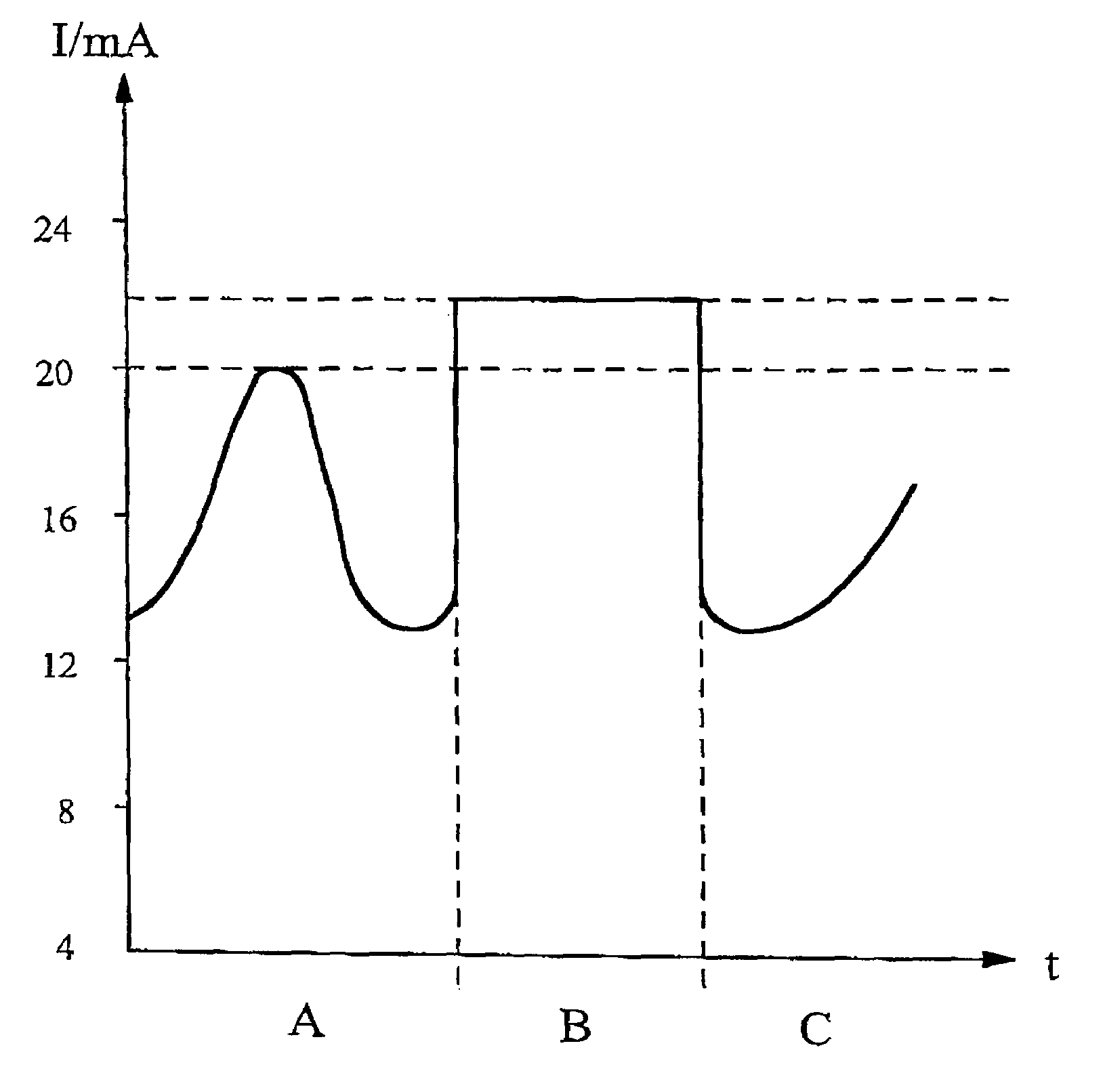
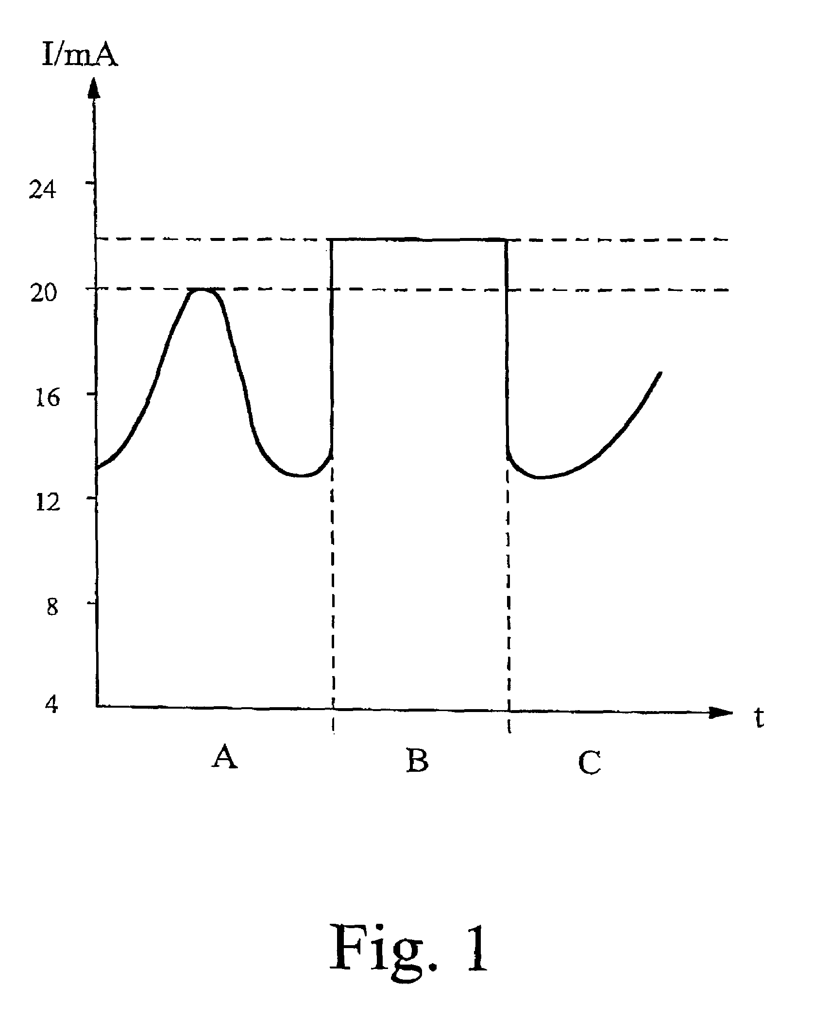
[0021]The first preferred embodiment of the invention comprises an electric measuring instrument configured as a two-wire device with an analog power connection through which, during normal measuring operations, flows a current of between 4 and 20 mA. That current serves to power the electric measuring instrument according to the first preferred embodiment of the invention, while also representing the measured value. In the FIG. 1 illustration, normal measuring operation of the measuring instrument according to the first preferred embodiment takes place in time domain A. There, the current changes as a function of time, where the current value can basically fluctuate between 4 and 20 mA, respectively indicating the lowest possible, the highest possible or an intermediate measured value.

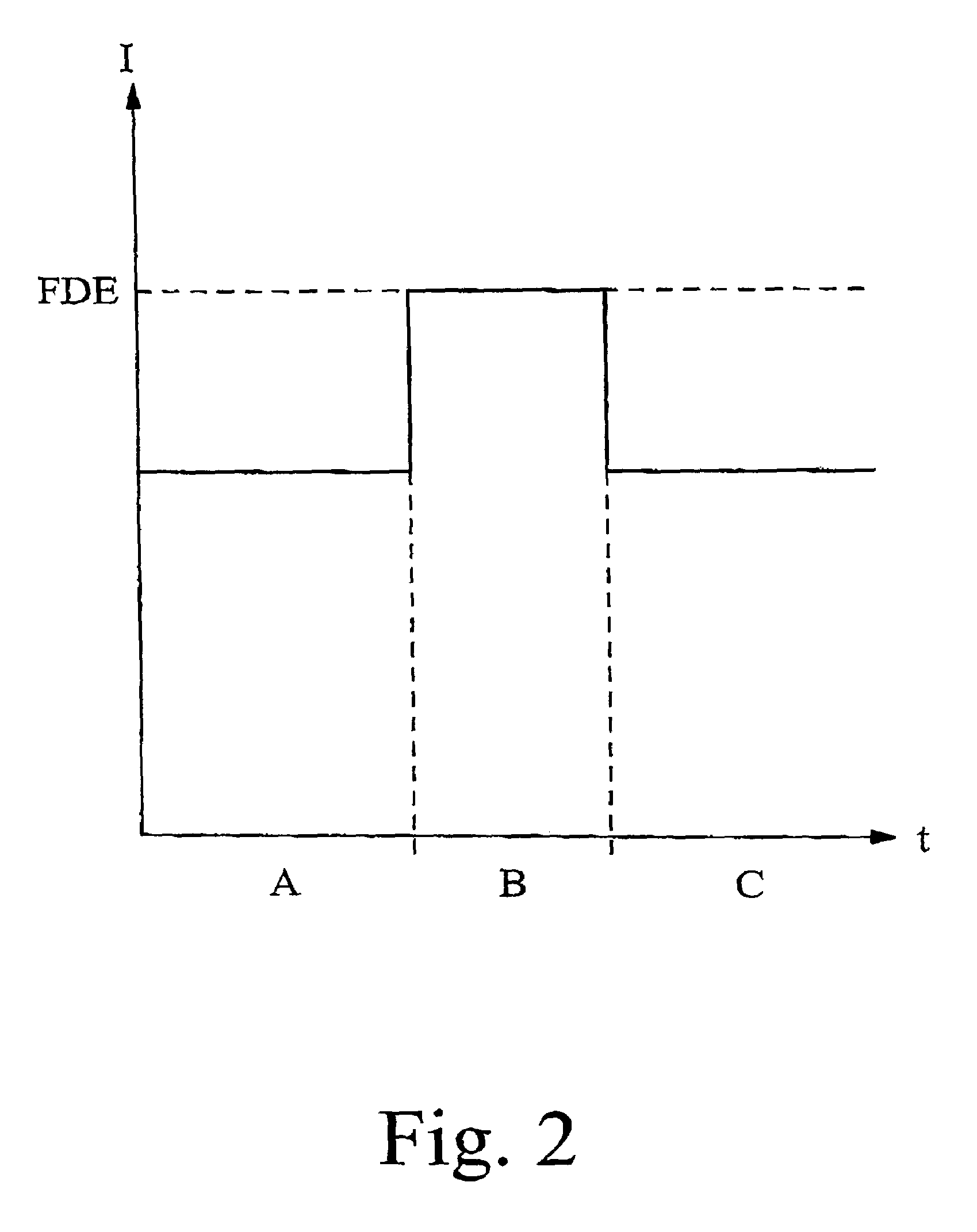
[0022]The transition from time domain A to time domain B triggers a special operational function, that being a software update for the measuring instrument. In the process, the maximum permissible pow...


PUM


Abstract

An electric device features a two-wire interface which two-wire interface serves to feed electric power to the electric device and also to transmit a signal, with the maximum power drawn via the two-wire interface in normal operation being restricted to a predefined upper limit. The permissible maximum power consumption of the electric device is automatically and temporarily increased beyond the predefined upper limit when the electric device is switched into a special operational function mode. The length of time in which the electric device is in the special operational function mode can thus be reduced.

Description

BACKGROUND OF THE INVENTION[0001]1. Field of the Invention[0002]This invention relates to an electric device with a two-wire interface, which duplex-conductor interface serves the dual purpose of feeding electric power to the electric device and transmitting a signal, with the maximum power drawn by the electric device via said two-wire interface during normal operation being restricted to a predefined upper limit. The invention also relates to a method for operating an electric device of that type.[0003]2. Background Information[0004]Electric devices of the type referred to above, featuring a two-wire interface, are also called two-wire devices. Many of these two-wire devices are measuring instruments. In normal operation, as in a routine measuring process, these two-wire instruments usually draw a predefined amount of current. In two-wire devices with an analog power input port, that predefined current is typically in the range from 4 to 20 mA, where in the case of a measuring ins...

Claims


Application Information

Patent Timeline
Patent Type & Authority Patents(United States)
IPC IPC(8): G06F1/26G06F1/32G06F1/28H02J1/06H02J13/00
CPCH02J1/06H02J13/0003Y04S20/18Y02B90/228Y02B90/20Y04S20/00
Inventor BROCKHAUS, HELMUT
Owner KROHNE MESSTECHNICK GMBH & CO KG
Why Eureka
Try Eureka