Self-centering chuck

a self-centering, chuck technology, applied in the direction of turning apparatus, sleeve/socket joint, vice, etc., can solve the problems of time-consuming and laborious maintenance in view of the required precision, and the gap between the clamping jaws remains very limited, so as to reduce the weight, facilitate the guiding, and reduce the effect of complexity

Active Publication Date: 2008-07-24
LANG TECHN
View PDF4 Cites 10 Cited by
  • Summary
  • Abstract
  • Description
  • Claims
  • Application Information

AI Technical Summary

Benefits of technology

[0005]The object of the present invention was therefore to provide a self-centering chuck for accurately fixing the position of workpieces to be machined on tables, which self-centering chuck guarantees expanded clamping paths, higher stability for guiding the slides and against twisting of the slides, a substantially reduced weight and less complicated logistics.

Problems solved by technology

One problem of the self-centering chucks of the class described is that the clamping jaws made integrally in one piece with the top side have only one clamping surface each suitable for clamping only.
Based on this, the clamping path between the clamping jaws remains very limited.
In addition, the sliding blocks screwed to the slides may become loose and tilt, which requires time-consuming and labor-intensive maintenance in view of the required precision.

Method used


Image

  • Self-centering chuck
  • Self-centering chuck
  • Self-centering chuck

Examples


Embodiment Construction

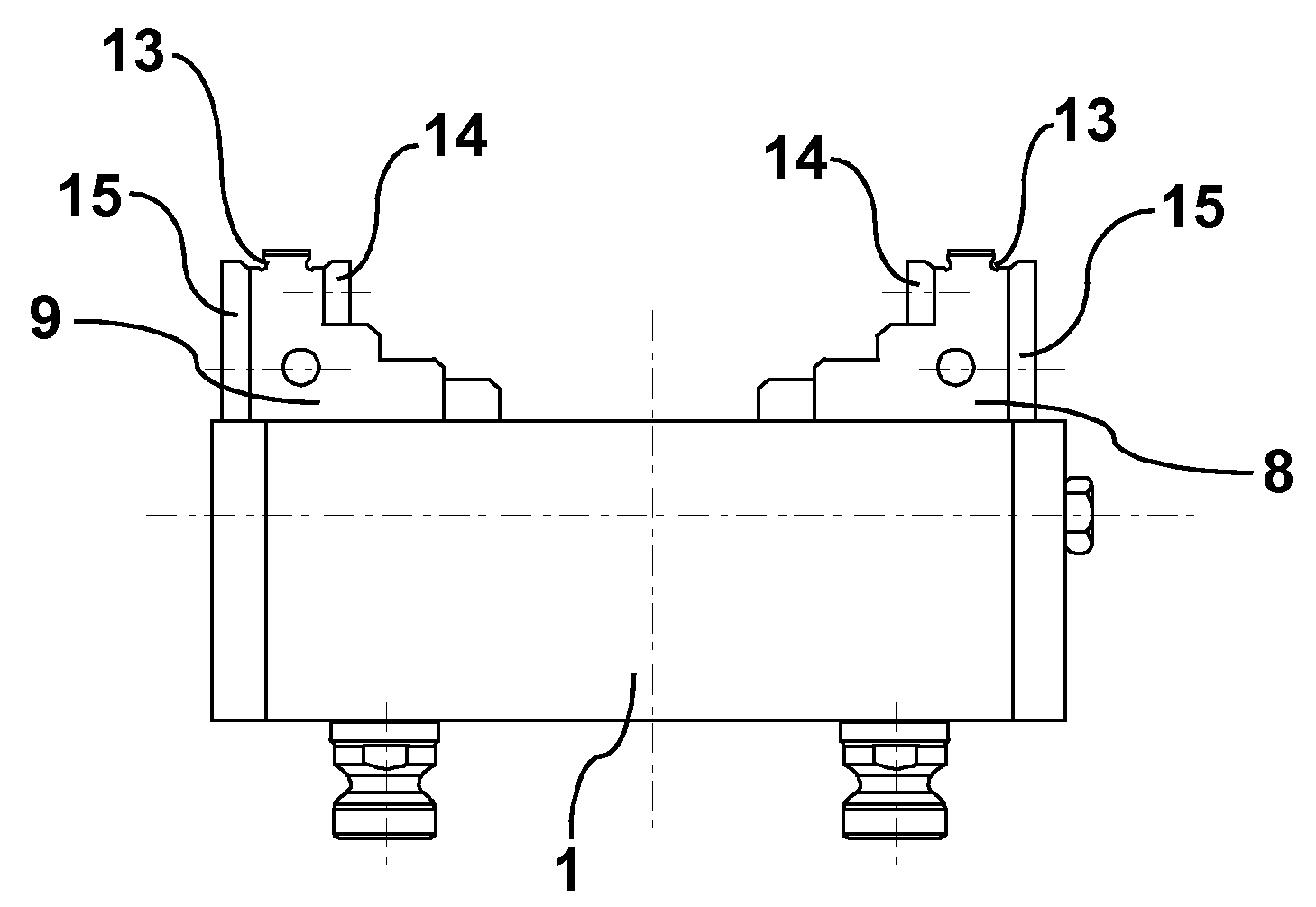
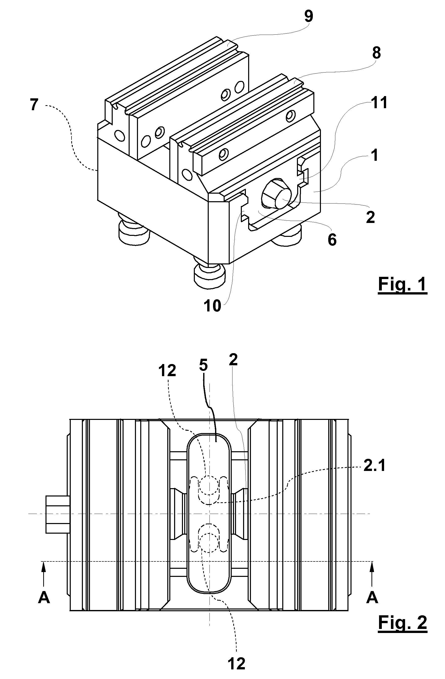
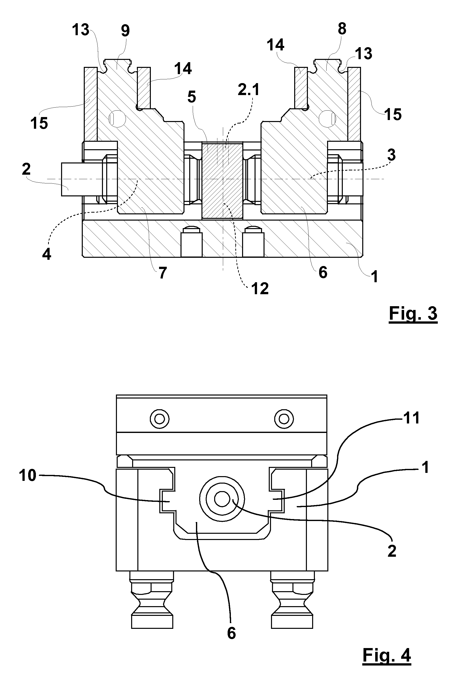
[0018]Referring to the drawings in particular, the exemplary embodiment shown in FIG. 1 is a self-centering chuck with a basic body 1, for example, one made of aluminum, in which two sliding blocks extending in parallel in the axial direction are arranged. Preferably two slides 6, 7 are provided in the head area with clamping jaws 8, 9 made integrally in one piece, which are provided, according to FIG. 3, for example, with special contours 13, and one side of which has a support surface 14 each and the opposite side of which has an auxiliary stop 15 each. A threaded spindle 2 is provided, according to FIG. 2 and FIG. 3, with a groove 2.1, which is made integrally in one piece between two external threads 3 and 4 and surrounds the circumference of the threaded spindle 2. The threaded spindle 2 can be fixed and locked on the basic body 1 by means of the groove 2.1 with preferably two fastening means 12 arranged opposite each other and is centered via a central piece 5 arranged central...


PUM


Abstract

A self-centering chuck is provided for accurately fixing the position of workpieces on tables. The chuck has a basic body with guide grooves, a threaded spindle with right-handed and left-handed external threads and a centrally arranged groove, two slides screwed onto an external thread each with a clamping jaw each in the head area and with sliding blocks in the foot area. The slides are guided axially in the guide grooves and on the threaded spindle. The threaded spindle is centered in a central piece and can be fixed and locked on the basic body and on the central piece by fastening means guided in the groove. The clamping jaws arranged on the head side on the slides have clamping surfaces on both sides and can be used on both sides. The slides can be screwed on both sides onto left-handed and right-handed external threads of the threaded spindle.

Description

CROSS REFERENCE TO RELATED APPLICATIONS[0001]This application claims the benefit of priority under 35 U.S.C. §119 of German Patent Application DE 10 2007 003 673.8 filed Jan. 18, 2007, the entire contents of which are incorporated herein by reference.FIELD OF THE INVENTION[0002]The present invention pertains to a self-centering chuck for accurately fixing the position of workpieces on tables.BACKGROUND OF THE INVENTION[0003]Self-centering chucks are known, which comprise a basic body consisting of a steel casting with guide grooves, a threaded spindle, which is mounted rotatably about its longitudinal axis and has a right-handed external thread in a first axial area and a left-handed external thread in a second axial area and is provided centrally with a groove surrounding the circumference of the threaded spindle, two slides screwed onto an external thread each of the threaded spindle with a clamping jaw each arranged in the head area, which are guided movably in the axial directio...

Claims


Application Information

Patent Timeline
Patent Type & Authority Applications(United States)
IPC IPC(8): B23B31/16
CPCB25B1/103B25B1/2405Y10T279/1973Y10T279/1986Y10T279/1913
Inventor LANG, GUNTER
Owner LANG TECHN
Why Eureka
Try Eureka