Ultrasonic motor and pressing mechanism of ultrasonic vibrator

a technology of ultrasonic vibrators and ultrasonic motors, which is applied in piezoelectric/electrostrictive/magnetostrictive devices, electrical apparatuses, electrical devices, etc., can solve the problem that the driven member cannot be driven with high driving efficiency, and achieve high efficiency

Inactive Publication Date: 2008-07-24
OLYMPUS CORP
View PDF8 Cites 32 Cited by
  • Summary
  • Abstract
  • Description
  • Claims
  • Application Information

AI Technical Summary

Benefits of technology

[0009]The present invention has been achieved in light of the circumstances described above, and an object thereof is to provide an ultrasonic motor and a pressing mechanism of an ultrasonic vibrator in which it is possible to

Problems solved by technology

Accordingly, although it is possible to balance the contact pressure between the driven member and the ultrasonic vibrator by applyi

Method used


Image

  • Ultrasonic motor and pressing mechanism of ultrasonic vibrator
  • Ultrasonic motor and pressing mechanism of ultrasonic vibrator
  • Ultrasonic motor and pressing mechanism of ultrasonic vibrator

Examples


Embodiment Construction

[0038]An ultrasonic motor 1 and a pressing mechanism 5 of an ultrasonic vibrator 2 according to an embodiment of the present invention will be described below with reference to FIGS. 1 to 7.

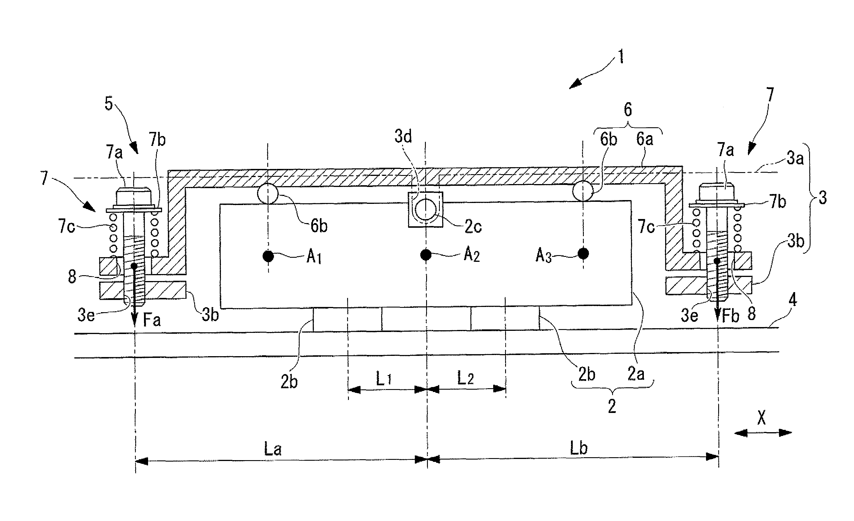
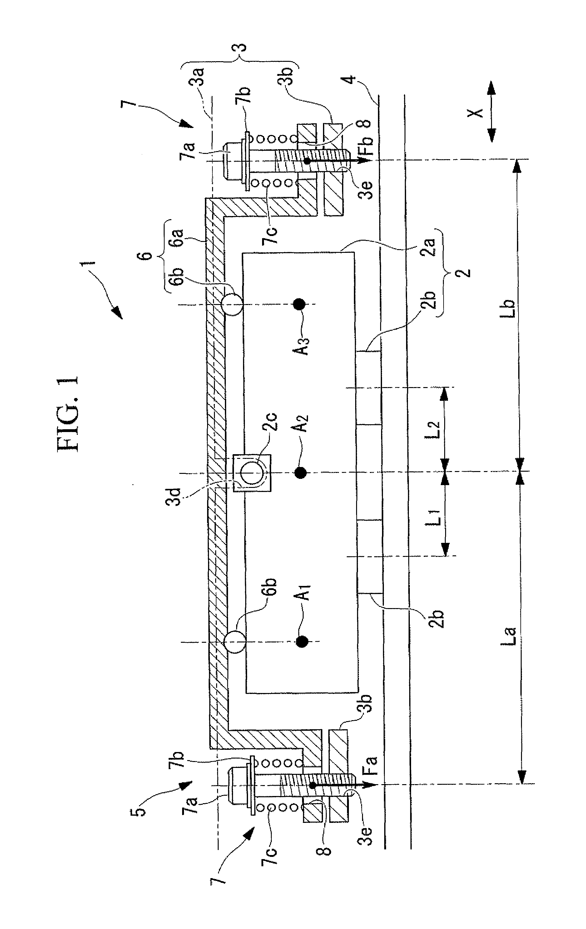
[0039]As shown in FIG. 1, the ultrasonic motor 1 according to this embodiment includes the ultrasonic vibrator 2, holders 3 for supporting the ultrasonic vibrator 2, a driven member 4 which is in contact with the ultrasonic vibrator 2 and which is driven relative to the ultrasonic vibrator 2, and the pressing mechanism 5 for pressing the ultrasonic vibrator 2 against the driven member 4.

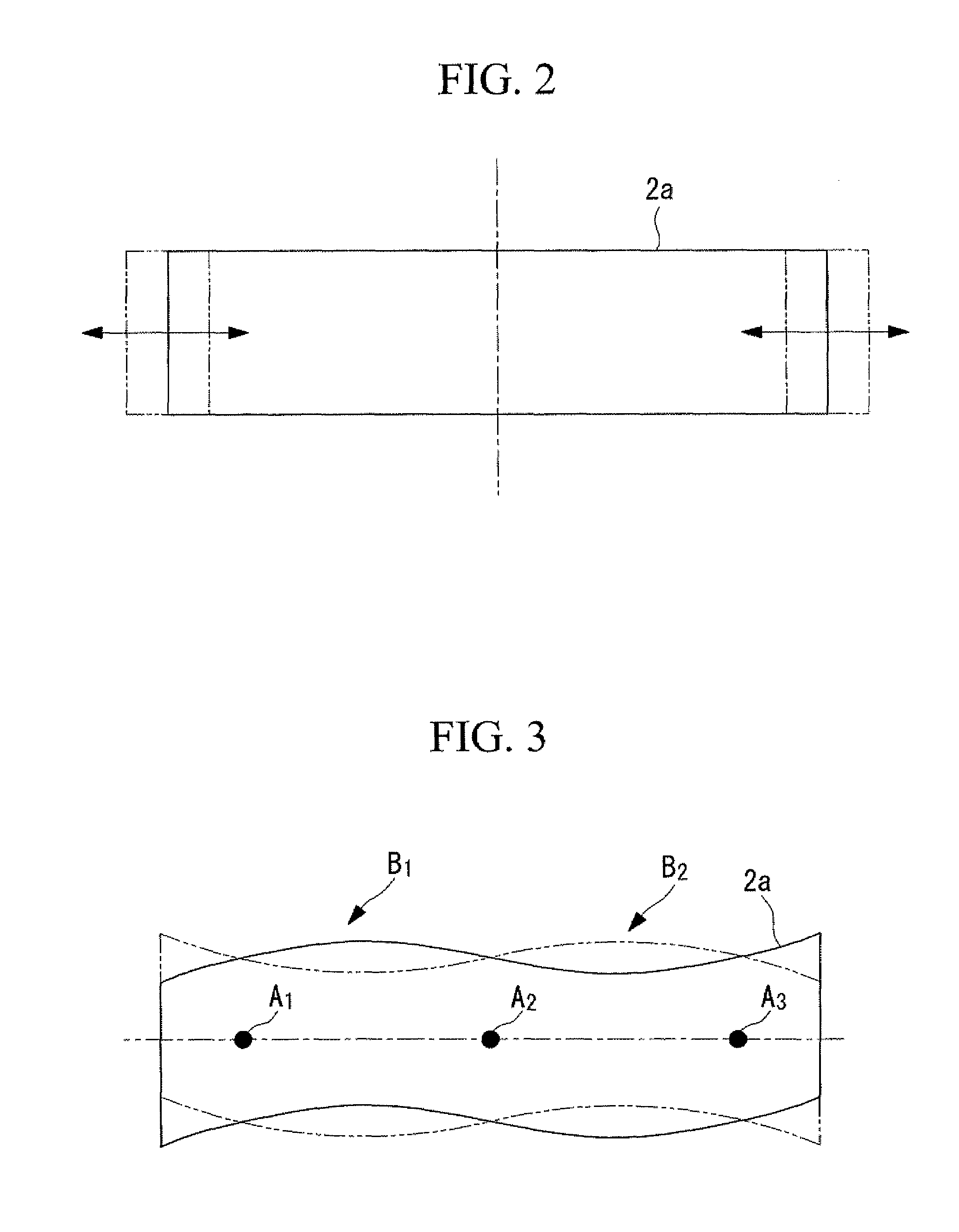
[0040]The ultrasonic vibrator 2 includes a rectangular-block-shaped piezoelectric layered member 2a, two friction-contact members (sliding members) 2b, and guide pins 2c. The piezoelectric layered member 2a is made up of a stack of rectangular piezoelectric ceramic sheets. On one side of each of the piezoelectric ceramic sheets, sheets of inner electrodes are provided. The friction-contact members 2b are bonded to...


PUM


Abstract

Contact pressures between a driven member and an ultrasonic vibrator are balanced, making the driving characteristics in the forward and reverse directions uniform, and the driven member is driven with high driving efficiency. The invention provides a pressing mechanism of an ultrasonic vibrator for pressing sliding members against a driven member, the sliding members being provided at two or more positions corresponding to antinodes of a standing wave vibration of the ultrasonic vibrator. The pressing mechanism includes a pressing member configured to make contact with the ultrasonic vibrator at two or more positions corresponding to nodes of the standing wave vibration of the ultrasonic vibrator; and pressing-force adjusting units configured to adjustably apply pressing forces, which press the sliding members against the driven member, to the pressing member at two or more separate positions in the direction of a gap between the two or more nodes of the standing wave.

Description

BACKGROUND OF THE INVENTION[0001]1. Field of the Invention[0002]The present invention relates to an ultrasonic motor and to a pressing mechanism of an ultrasonic vibrator.[0003]This application is based on Japanese Patent Application No. 2007-010336, the content of which is incorporated herein by reference.[0004]2. Description of Related Art[0005]Ultrasonic motors, which are compact and have high torque, long stroke, and high resolution compared to electromagnetic motors, are commonly used in the related art.[0006]Ultrasonic motors are motors for driving a driven member with a friction force that is generated between an ultrasonic vibrator and the driven member by pressing the ultrasonic vibrator against the driven member. A known pressing mechanism for pressing an ultrasonic vibrator against a driven member in the related art is disclosed, for example, in Japanese Unexamined Patent Application, Publication No. HEI-11-312017.[0007]This pressing mechanism includes compression springs...

Claims


Application Information

Patent Timeline
IPC IPC(8): H02N2/04
CPCH01L41/0906H01L41/053H02N2/004H02N2/0055H02N2/026
Inventor SAKAMOTO, TETSUYUKI
Owner OLYMPUS CORP
Why Eureka
Try Eureka