Flow Measurement Using NMR

a flow measurement and nuclear magnetic resonance technology, applied in wave based measurement systems, instruments, reradiation, etc., can solve the problems of inability to accurately measure fid signals, signals that decay too fast for reliable detection, and the complexity of obtaining accurate measurements

Active Publication Date: 2008-07-24
SCHLUMBERGER TECH CORP
View PDF25 Cites 22 Cited by
  • Summary
  • Abstract
  • Description
  • Claims
  • Application Information

AI Technical Summary

Problems solved by technology

Moving pails, such as a turbine, disturb the flow pattern of the fluid, thus increasing the complexity of obtaining accurate measurements.
However, the FID signal is difficult to measure using permanent magnets because static magnetic field variations will result in signals that decay too fast for reliable detection.
Moreover, the King et al. methods for determining flow

Method used


Image

  • Flow Measurement Using NMR
  • Flow Measurement Using NMR
  • Flow Measurement Using NMR

Examples


Embodiment Construction

[0062]Specific embodiments of the invention will now be described with reference to the figures. Like elements in the various Figures will be referenced with like numbers for consistency.

[0063]Embodiments of the invention relate to a method and apparatus for measuring flow properties, particularly a flow velocity, based on measuring a phase of an NMR signal. To obtain an NMR signal with a measurable phase, a magnetic field gradient pulse is used to shift the phase of the NMR signal.

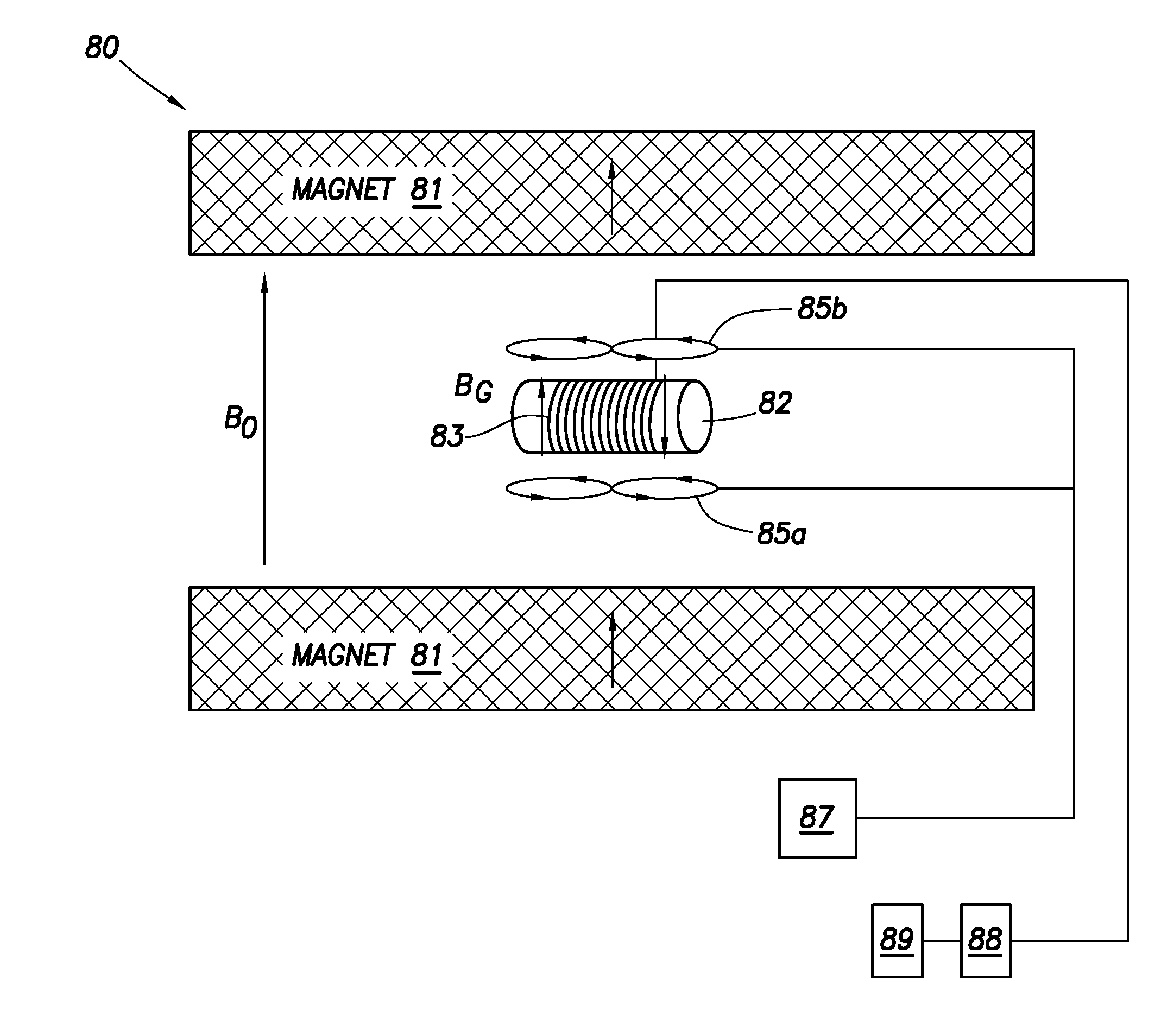
[0064]U.S. Pat. No. 7,053,611, issued to Freedman on May 30, 2006, and assigned to the assignee of the present invention, has disclosed an NMR sensor that includes means for generating a pulsed magnetic field gradient (PFG). This NMR sensor exploits NMR signal amplitude information, but not phase information. The structure of the NMR sensor and pulse sequences disclosed by Freedman in the '611 patent is described in the following paragraphs with reference to FIG. 6 to facilitate the understanding of a bas...


PUM


Abstract

A nuclear magnetic resonance (NMR) method is used to determine a velocity distribution or velocity image of a flowing fluid in a downhole environment. The method comprises applying a radio frequency pulse sequence; applying a magnetic field gradient magnetic field and a gradient pulse duration; measuring a NMR signal; determining a phase characteristic of the NMR signal; and determining the velocity distribution or image of the fluid using the determined phase characteristic, the magnetic field gradient pulse parameters, and a time delay between gradient pulses.

Description

CROSS-REFERENCE TO RELATED APPLICATIONS[0001]This application claims priority from and the benefit of U.S. Provisional Patent Application No. 60 / 877,946, filed Dec. 28, 2006.BACKGROUND OF INVENTION[0002]1. Field of the Invention[0003]The invention relates generally to flow measurement methods and systems. In particular, embodiments relate to flow measurements using Nuclear Magnetic Resonance (NMR) instruments.[0004]2. Background Art[0005]In industries where a flow of fluid is involved, measurements of flow parameters such as flow velocity and fluid viscosity are often required. Conventional flow measurement technologies include turbine flow meters and positive-displacement flow meters, both of which involve placement of moving parts in the flowing fluid. Moving pails, such as a turbine, disturb the flow pattern of the fluid, thus increasing the complexity of obtaining accurate measurements.[0006]Non-invasive (low measurements such as ultrasonic meters and NMR sensors have certain ad...

Claims


Application Information

Patent Timeline
IPC IPC(8): G01V3/14
CPCG01N24/081G01R33/56308G01R33/5613
Inventor GANESAN, KRISHNAMURTHY
Owner SCHLUMBERGER TECH CORP
Why Eureka
Try Eureka