
Powered device analysis and power control in a Power-over-Ethernet system

a power-over-ethernet and power-control technology, applied in data switching networks, digital transmission, transportation and packaging, etc., can solve the problems of system inefficiency, pse chip, phy chip, and high cos

Active Publication Date: 2008-07-24
AVAGO TECH INT SALES PTE LTD
View PDF6 Cites 27 Cited by
  • Summary
  • Abstract
  • Description
  • Claims
  • Application Information

AI Technical Summary

Problems solved by technology

This system is inefficient in that, with the PSE chip separate from the PHY, a host CPU needs to collect information from the PSE chip and send it to the PSE PHY chip in order for PoE status to be displayed.
In some systems, the PSE chip drives the LED independently of the PHY chip, which is expensive.

Method used


Image

  • Powered device analysis and power control in a Power-over-Ethernet system
  • Powered device analysis and power control in a Power-over-Ethernet system
  • Powered device analysis and power control in a Power-over-Ethernet system

Examples


Embodiment Construction

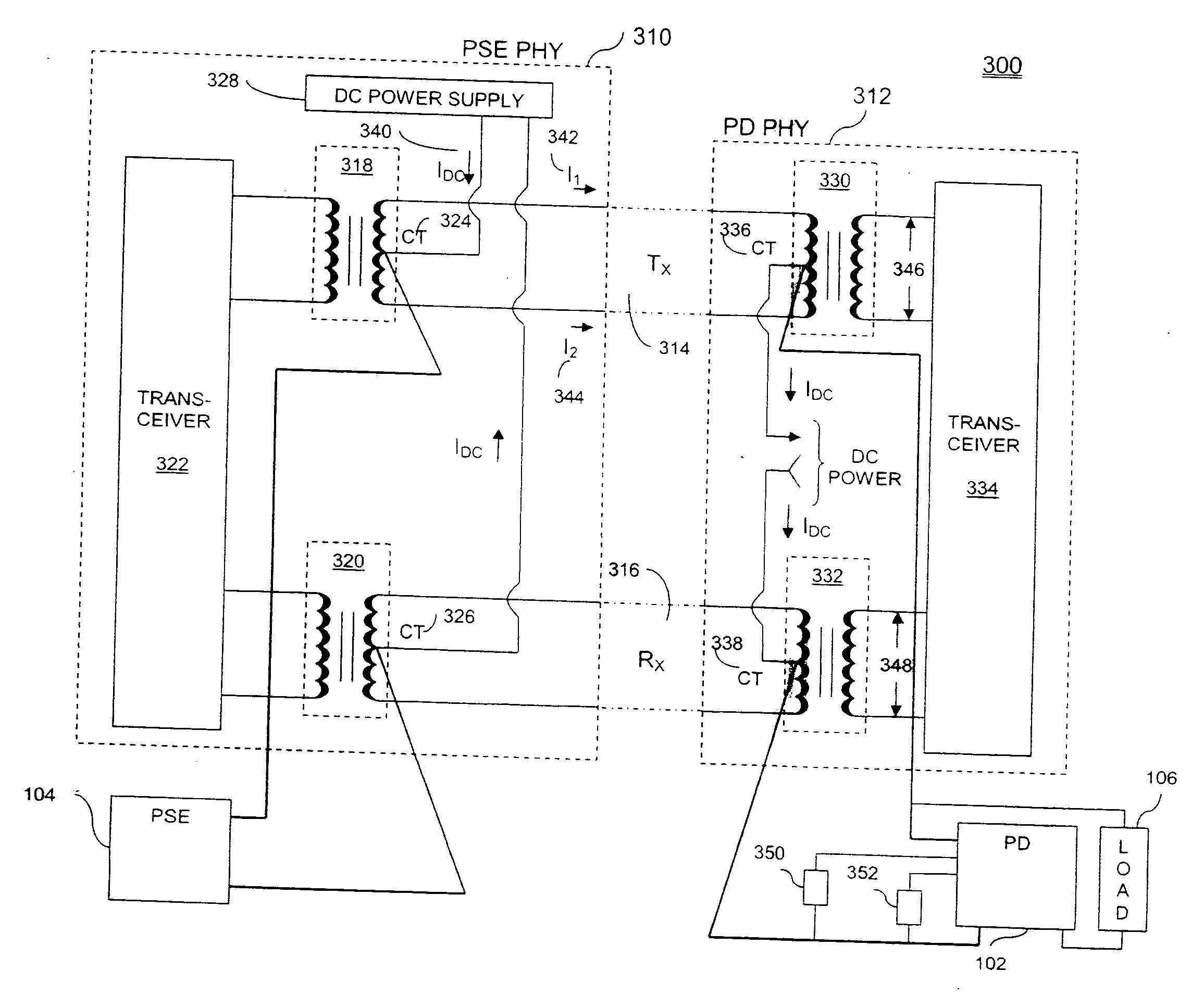
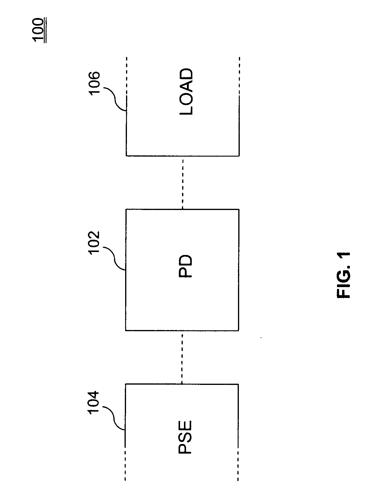
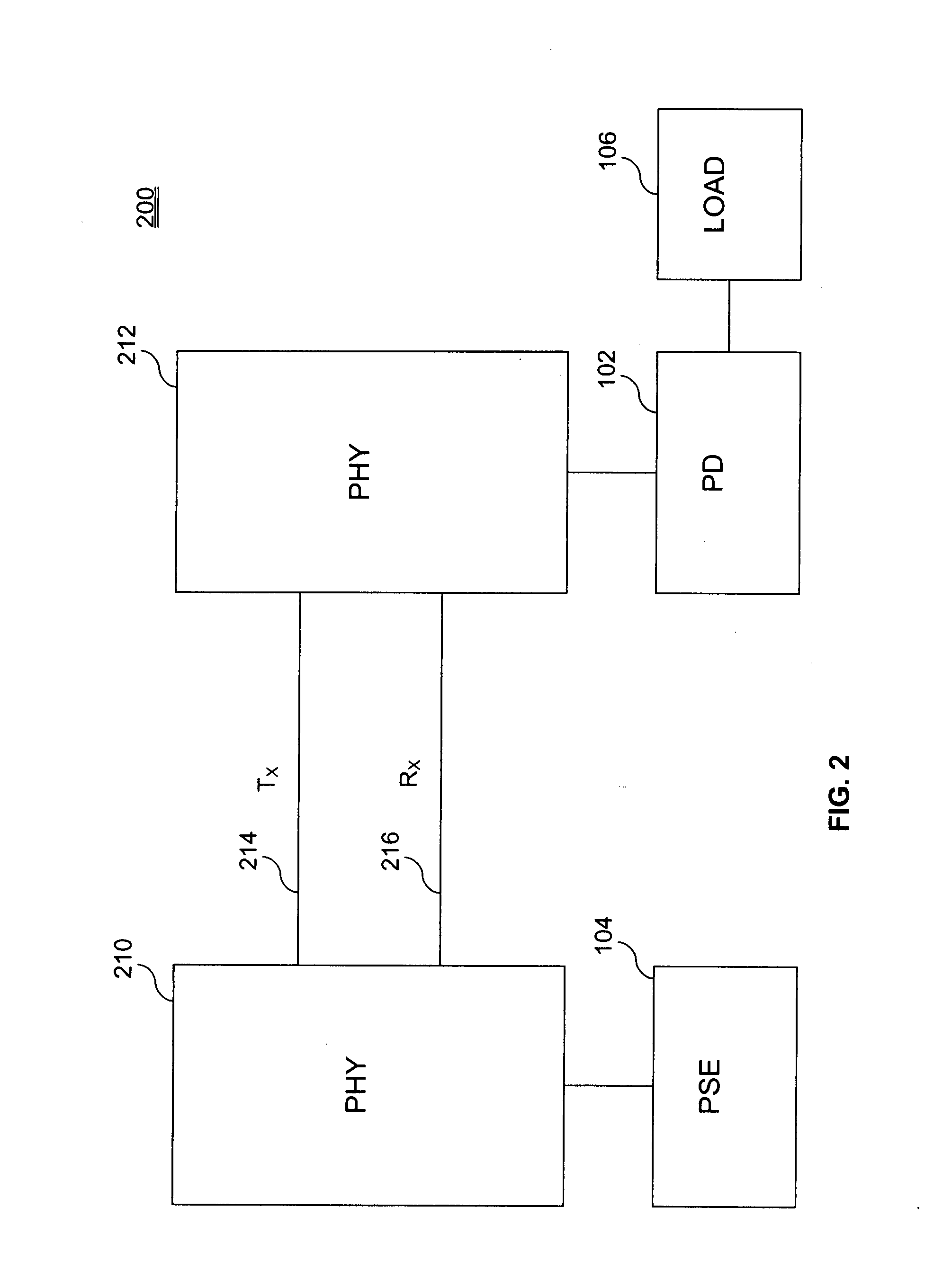
[0017]The following describes powered device (PD) analysis in a Power-over-Ethernet (PoE) system. FIG. 1 illustrates a conventional powered device chip architecture 100, with a powered device chip (PD) 102 connected to a power sourcing equipment chip (PSE) 104 and a load 106. The PSE 104 analyzes characteristics of PD 102, and can, for example, monitor and control the application of power to PD 102 based on those characteristics. In a more specific example, PSE 104 can detect and validate a compatible PD, determine a power classification signature for the validated PD, supply power to the PD, monitor the power, and reduce or remove the power from the PD when the power is no longer requested or required. During detection, if PSE 104 finds a PD to be non-compatible, PSE 104 can prevent the application of power to that PD, protecting the PD from possible damage.

[0018]In a conventional PoE system, PSE 104 is connected to PD 102 through an Ethernet interface, as shown in PD chip architec...


PUM


Abstract

A system and method of analyzing a powered device (PD) in a Power-over-Ethernet (PoE) system are presented. The system includes an Ethernet interface having a physical layer (PHY) chip capable of providing a signal pulse in addition to physical layer 1 functions. The system further includes a pulse transformer, coupled to the PHY chip, capable of relaying the signal pulse provided by the PHY chip to the PD via the transmit line and a second PHY chip. The first PHY chip receives one or more return pulse signals from the PD, analyzes characteristics such as voltage and / or frequency of the return pulse signal(s), and determines attributes of the PD based on those characteristics. The attributes can include powered device validity and power classification. A method of supplying power to a PD is also presented.

Description

CROSS REFERENCE TO RELATED APPLICATIONS[0001]This application claims benefit of U.S. Provisional Patent Appl. No. 60 / 878,676, filed on Jan. 5, 2007, which is incorporated by reference herein in its entirety.BACKGROUND OF THE INVENTION[0002]1. Field of the Invention[0003]The present invention generally relates to Power-over-Ethernet (PoE) systems. More specifically, the present invention relates to analysis of PoE devices (or Powered Devices (PD)) in a PoE system.[0004]2. Related Art[0005]In conventional PoE systems, a power sourcing equipment (PSE) chip analyzes characteristics of a PD and can control the supply of power to the PD. This analysis and control by a PSE chip occurs through an Ethernet interface including a PSE physical layer (PHY) chip and a PD PHY chip with a data link in between. In this system, the PSE PHY chip typically handles physical layer 1 functions and drives the link, activity, speed, and PoE light-emitting diodes (LEDs). This system is inefficient in that, w...

Claims


Application Information

Patent Timeline
IPC IPC(8): H04L12/56
CPCH04L12/66
Inventor HUSSAIN, ASIFPANDYA, MANISHAROOHPARVAR, FARZANPERZOW, JOHN
Owner AVAGO TECH INT SALES PTE LTD
Learn More