Image coding apparatus, image decoding apparatus, image processing apparatus and methods thereof

a technology of image processing and coding apparatus, applied in the field of image processing apparatus and methods thereof, can solve the problems of less efficient coding, lower compression rate, unnatural image, etc., and achieve the effect of increasing the resolution of the first still image, high resolution, and high compression ra

Active Publication Date: 2008-07-24
SOVEREIGN PEAK VENTURES LLC
View PDF1 Cites 86 Cited by
  • Summary
  • Abstract
  • Description
  • Claims
  • Application Information

AI Technical Summary

Benefits of technology

[0060]It is possible to prevent the second still picture to be used as the reference image from being accidentally deleted.
[0061]The resolution of the first still image can be changed to a high resolution, and furthermore, can be coded at a higher compression rate. For example, although the resolution of the first still image is increased, it is possible to reduce the file size after coding.
[0062]The image coding apparatus and method according to the present invention can decode a bit stream of the first still image coded at a high compression rate.
[0063]In addition, the image decoding apparatus and the image decoding method according to the present invention can assure full decoding in

Problems solved by technology

The still image coding methods and intra image coding methods have a problem that coding is less efficient (the compression rate is lower) than the inter prediction coding method using the motion compensation which is adapted to the MPEG-2 and the H.264.
However, when the removed part is to be completed with an image in a complex shape and when the removed part is to be completed with an image which does not exist in the non-removed part, there is another problem that the completed image results in an un

Method used


Image

  • Image coding apparatus, image decoding apparatus, image processing apparatus and methods thereof
  • Image coding apparatus, image decoding apparatus, image processing apparatus and methods thereof
  • Image coding apparatus, image decoding apparatus, image processing apparatus and methods thereof

Examples


first embodiment

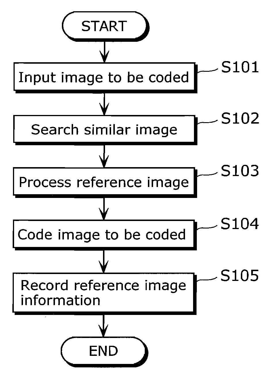
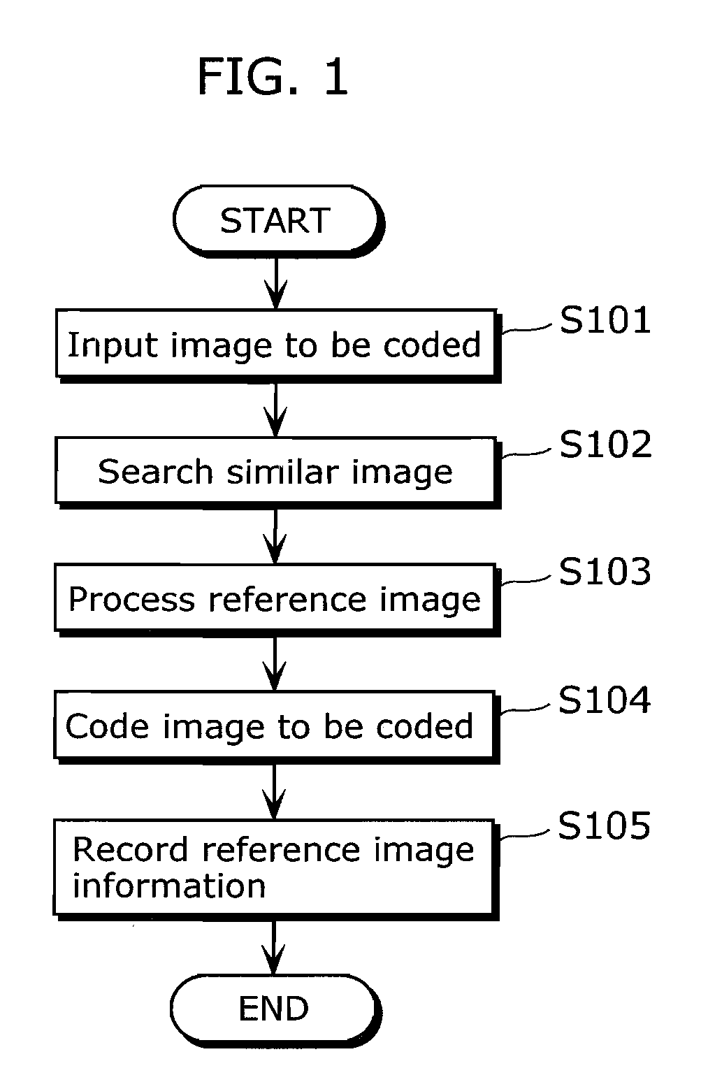
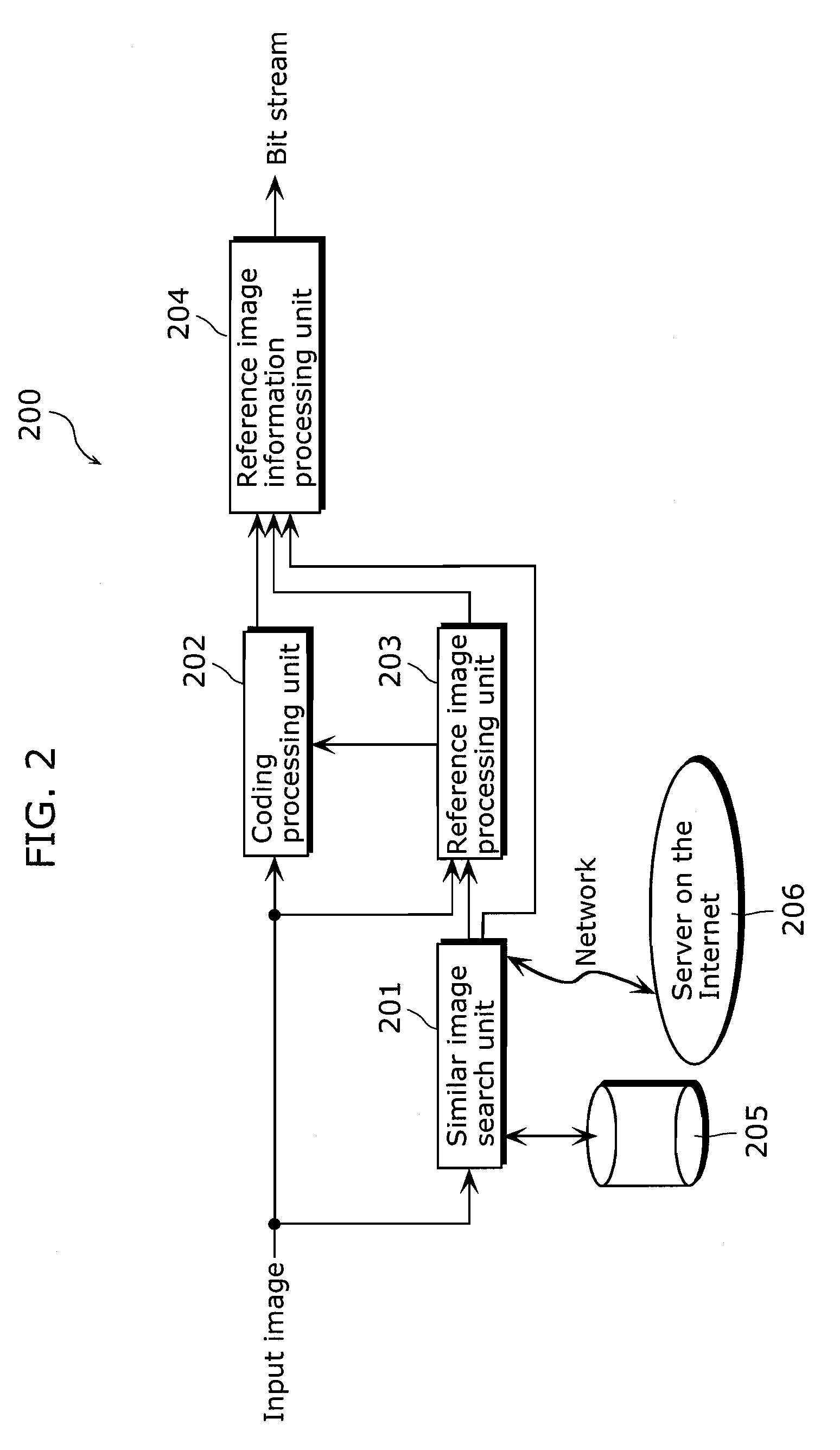
[0124]FIGS. 1 and 2 are a flowchart and a block diagram respectively showing an order of processing in the image processing method according to the present invention. As shown in FIG. 2, the image coding apparatus according to the present invention includes a similar image search unit 201, a coding processing unit 202, a reference image processing unit 203, a reference image information processing unit 204, and a storage medium 205.

[0125]As shown in FIG. 2, an image coding apparatus 200 includes the similar image search unit 201, the coding processing unit 202, the reference image processing unit 203, the reference image information processing unit 204, and the storage medium 205.

[0126]The similar image search unit 201 searches at least one of a second still image (hereinafter referred to as a similar image) which is similar to the first still image which is to be compressed and coded (hereinafter referred to as an input image) from a group of images. The group of images is still pi...

second embodiment

[0174]FIGS. 10 and 11 are respectively a flowchart and a block diagram showing an order of processing of the image decoding method according to the present invention. As shown in FIG. 11, the image coding apparatus according to the present invention includes a reference image obtainment unit 1001, a decoding processing unit 1002, a reference image processing unit 1003, and a bit stream processing unit 1004.

[0175]The input bit stream is a bit stream generated in the image coding method according to the present invention, and the configurations are shown in FIG. 9. The bit stream is inputted to the bit stream processing unit 1004 (Step S901). The bit stream processing unit 1004 divides the bit stream into the image bit stream and the additional information bit stream. The image bit stream is outputted to the decoding processing unit 1002 and the information on the source of the reference image in the additional information bit stream is outputted to the reference image obtainment unit...

third embodiment

[0189]FIG. 15 is a flowchart showing the order of processing in the data management method according to the present invention. The data management method according to the present invention is a method for handling image data on a device and a computer in which the image data (file) generated in the image coding method according to the present invention is stored (hereinafter simply referred to as devices).

[0190]When the user inputs an instruction for deleting an image in the device holding the image data (step S1401), the device searches “other image data which is coded using the image data to be deleted as the reference image” (step S1402). Here, the search can be performed, for example, by confirming the decoding method of all image data in the device one by one, or by creating a table showing the coding method of the image data in the device in advance and using the table. When the searched object is found (Yes in step S1403), the device notifies the user of the information, and ...


PUM


Abstract

The image coding apparatus according to the present invention includes: a similar image search unit 201 which searches at least one second still image which is similar to a first still image; a coding processing unit 202 which generates a predictive image for the first still image using the at least one second still image as the reference image, and codes the difference between the first still image and the predictive image; and a reference image information processing unit 204 which adds information which indicates the location of at least one of the second still image to the bit stream.

Description

BACKGROUND OF THE INVENTION[0001](1) Field of the Invention[0002]The present invention relates to an image coding apparatus which compresses a still image with high efficiency, an image decoding apparatus, an image processing apparatus and methods thereof.[0003](2) Description of the Related Art[0004]As a method for compression coding a still image with high efficiency, the JPEG and the JPEG 2000 are set as standards (for example, see ITU-T Rec. T.81, Information Technology—Digital Compression and Coding of Continuous-Tone Still Images—, 1992.). In addition, the moving picture coding standards such as MPEG-2, H.264 and others employs an intra coding method in which the image which is to be an access point is coded without referring to other image is used.[0005]An image completion method for generating a completed image by removing a part of image from the image taken by a digital camera and the like and covering the removed part with completion pixels (For example, I. Drori, D. Choh...

Claims


Application Information

Patent Timeline
IPC IPC(8): G06K9/36H04N19/50H03M7/36H04N1/417H04N19/11H04N19/132H04N19/134H04N19/136H04N19/139H04N19/14H04N19/189H04N19/196H04N19/423H04N19/46H04N19/503H04N19/51H04N19/513H04N19/577H04N19/593H04N19/61H04N19/63H04N19/70H04N19/91
CPCG06F17/30247H04N19/105H04N19/176H04N19/70H04N19/46H04N19/51H04N19/59H04N19/60H04N19/107H04N19/132H04N19/162H04N19/17H04N19/54H04N19/61G06F16/583
Inventor KONDO, SATOSHI
Owner SOVEREIGN PEAK VENTURES LLC
Why Eureka
Try Eureka