Image processing apparatus, image processing system, imaging apparatus and image processing method

a technology of image processing which is applied in the field of image processing apparatus, image processing system, imaging apparatus, and image processing method, can solve the problems of increasing manufacturing cost, circuit scale, and power consumption, and so as to reduce reduce the capacity of the memory for storing these correction data. , the effect of reducing the amount of necessary correction data

Inactive Publication Date: 2008-07-24
SONY CORP
View PDF13 Cites 18 Cited by
  • Summary
  • Abstract
  • Description
  • Claims
  • Application Information

AI Technical Summary

Benefits of technology

[0032]The present invention is accomplished in view of such respects. It is desirable to provide an image processing apparatus enable to correct distortion occurring in a captured image and enhance the image quality thereof by a small-scale processing circuit even if an optical zoom is utilized.
[0046]Further, the distortion correction parameters for distortion correction, which are compressed in a zooming direction, and a horizontal direction and a vertical direction of an image, are decompressed in each of the directions according to the designated coordinate and the zoom positions, and utilized for correcting distortion of the image. Accordingly, the amount of necessary distortion correction data is reduced, while high precision distortion correction according to the zoom position can be achieved. Further, if the distortion correction processing of one line is performed, interpolation calculations of the correction parameters corresponding to the zooming direction and the vertical direction are performed in a horizontal retrace period. Then, interpolation calculation of the correction parameters corresponding to the horizontal direction is performed in an image effective period by using the obtained correction parameters. Accordingly, when the distortion correction processing is performed, processing load on the decompression processing of the correction parameters can be reduced. Consequently, the size of the decompression circuit and the manufacturing cost thereof can be suppressed. Additionally, the decompression processes respectively corresponding to the directions can be achieved by sharing a single decompression circuit.

Problems solved by technology

Accordingly, the apparatus of related art has drawbacks such as necessary computing power, circuit scale, and power consumption increase, and manufacturing cost rises.
It is difficult for the apparatus of related art to deal with such a case.
However, according to this method, the smaller a data amount is changed by decreasing the number of partitioning points, the lower the distortion-correction precision becomes.
Therefore, this method has a problem in that the scale of the processing circuit is large.
However, in a case where the decoding of the distortion correction data is performed by following such procedure, an operation probability of the process in the zooming direction and the x-direction is low.
This has been one of causes of increase in the scale of a decoding circuit.

Method used


Image

  • Image processing apparatus, image processing system, imaging apparatus and image processing method
  • Image processing apparatus, image processing system, imaging apparatus and image processing method
  • Image processing apparatus, image processing system, imaging apparatus and image processing method

Examples


first embodiment

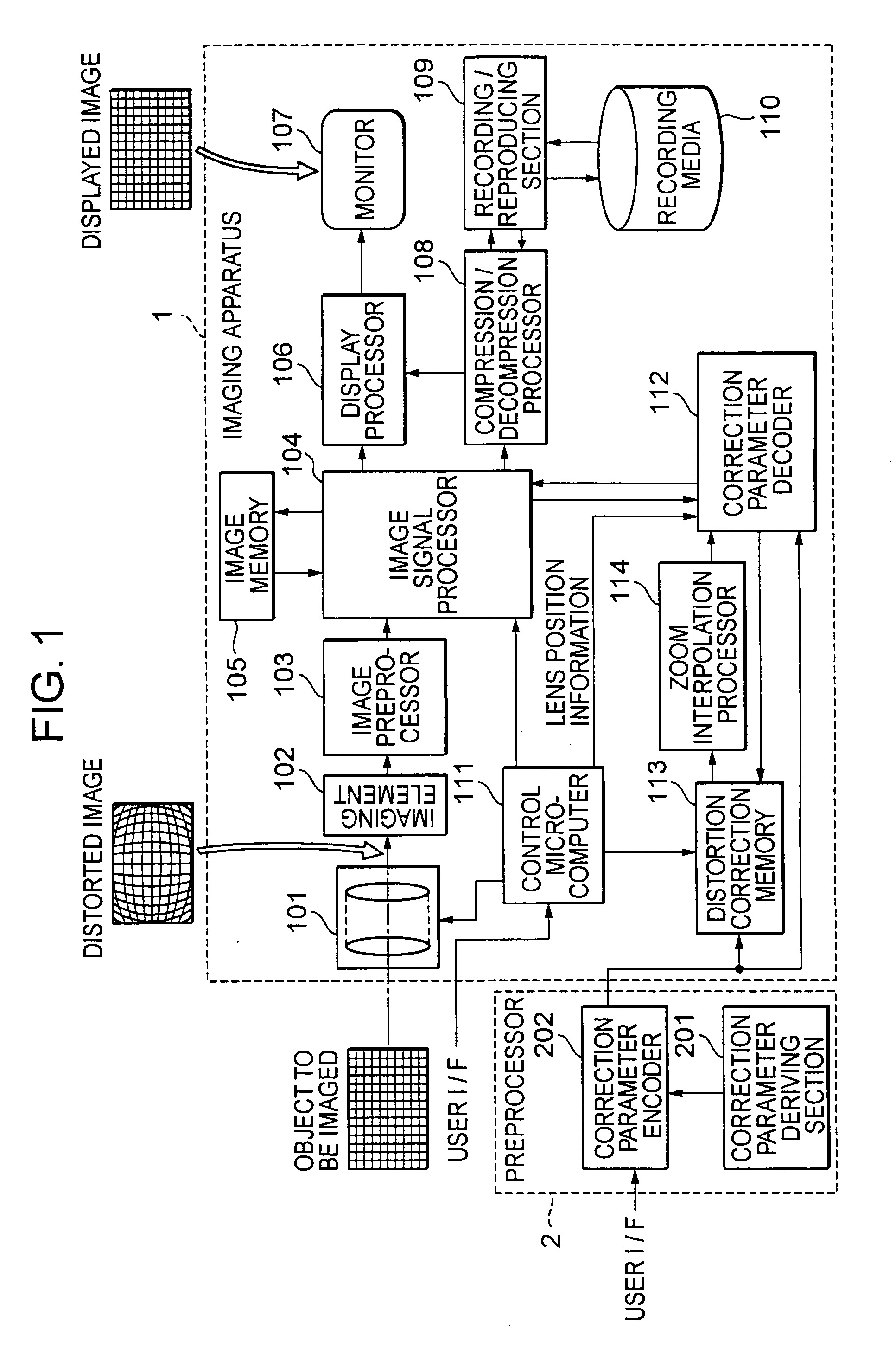
[0077]FIG. 1 is a block diagram showing an example of the configuration of an imaging system according to a first embodiment of the present invention.

[0078]The imaging system shown in FIG. 1 is used for capturing an image and recording the image on a recording medium as digital data, and has an imaging apparatus 1 and a preprocessor 2.

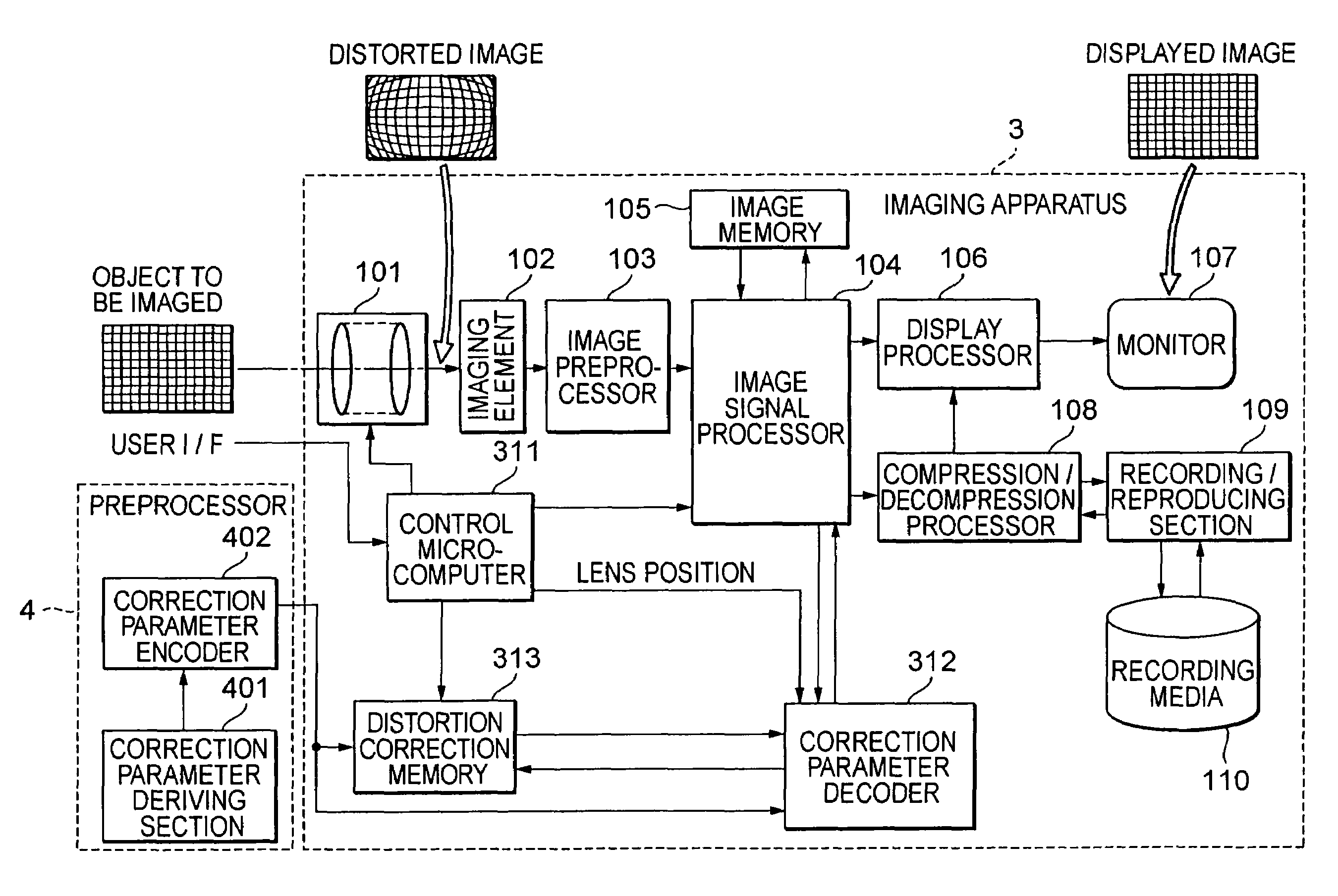
[0079]The imaging apparatus 1 has an optical block 101, an imaging element 102, an image preprocessor 103, an image signal processor 104, an image memory 105, a display processor 106, a monitor 107, a compression / decompression processor 108, a recording / reproducing section 109, recording media 110, a control microcomputer (hereunder sometimes referred to simply as a microcomputer) 111, a correction parameter decoder 112, a distortion correction memory 113, and a zoom interpolation processor 114. Further, the preprocessor 2 has a correction parameter deriving section 201 and a correction parameter encoder 202.

[0080]In the imaging apparatus 1, the optica...

second embodiment

[0176]Hereinafter, a second embodiment of the present invention is described in detail by referring to the accompanying drawings.

[0177]In the first embodiment of the present invention, if image signals representing a captured image are displayed and recorded, a digital correction process is performed on optical distortion caused in an original image in the image signal processor 104. This optical distortion results from the optical characteristics of the lenses in the optical block 101. To correct such optical distortion, a digital process is performed on the captured image by using distortion correction coordinates set at each of pixels of the image according to the characteristics of the lenses. Accordingly, the captured image is corrected by performing the digital process.

[0178]It is necessary to set the distortion correction coordinates corresponding to each of all the pixels of the image. This results in a huge amount of data. Accordingly, these distortion coordinates are utili...

third embodiment

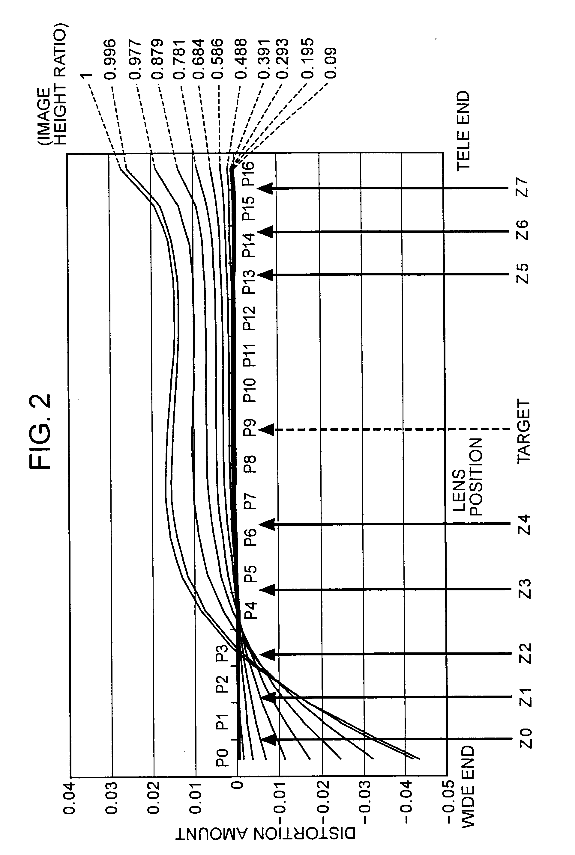
[0291]In the imaging systems according to the first and second embodiments, the distortion correction parameters are prepared corresponding to each of the zoom points of the optical zoom lens mechanism, and stored in the distortion correction memory 113. Accordingly, as compared with the system of prior art, an amount of data to be prepared is considerably reduced, and the capacity of the memory can be reduced. However, it is preferable to ensure a certain amount of memory capacity. Further, in a case where the imaging system is configured so that these distortion correction parameters are supplied from outside, a certain amount of communication capacity and computing power for calculating these values are needed. Accordingly, there is some demands for further reducing necessary memory capacity, communication capacity, computing power, and the cost thereof, and for ensuring the real-time capability thereof.

[0292]Meanwhile, in the first embodiment, the interpolation process is perfor...


PUM


Abstract

An image processing apparatus includes an zoom position acquiring section for acquiring a zoom position representing a lens position condition of the optical zoom mechanism on taking the inputted image, a zooming-direction decoding section for decompressing correction parameter associated with the zoom position, which is acquired by the zoom position acquiring section, according to a zoom compression parameter, into which a correction parameter for distortion correction corresponding to each lens position condition is compressed by utilizing zoom partitioning points at which lens position conditions of the optical zoom mechanism are sequentially partitioned into plural levels that are set between a wide-end and a tele-end and that include both ends, and an image correction section for correcting distortion of the inputted image according to the correction parameter decompressed by the zooming-direction decoding section.

Description

CROSS REFERENCES TO RELATED APPLICATIONS[0001]This application is a division of co-pending U.S. patent application Ser. No. 10 / 902,140 filed Jul. 30, 2004, claims priority to its priority documents No. 2003-288109 filed in the Japanese Patent Office on Aug. 6, 2003 and No. 2003-292725 filed in the Japanese Patent Office on Aug. 13, 2003, the entire contents of which being incorporated by reference herein.BACKGROUND OF THE INVENTION[0002]1. Field of the Invention[0003]The present invention relates to an image processing apparatus, an image processing system, an imaging apparatus, and an image processing method, which are used for correcting distortion of a captured image. More particularly, the present invention relates to an image processing apparatus, an image processing system, an imaging apparatus, and an image processing method, which are capable of performing distortion correction on an image, which is taken by using a converging lens group having an optical zoom mechanism, acc...

Claims


Application Information

Patent Timeline
Patent Type & Authority Applications(United States)
IPC IPC(8): G06K9/40H04N5/225G02B7/04G03B30/00G06T3/40
CPCG06T3/0018H04N23/00
Inventor NOSE, ATSUSHIAOYAMA, KOJIKURATA, TOHRUWADA, KIMITAKA
Owner SONY CORP
Why Eureka
Try Eureka