Rescue and locational determination equipment

a technology of location determination and rescue equipment, applied in special-purpose vessels, rafts, instruments, etc., can solve the problems of high cost, ineffectiveness, inefficiency and/or burden, flares and radio equipment suffer from numerous inefficiencies and burdens, etc., and achieve low cost, efficient and reliable

Inactive Publication Date: 2008-07-31
HATFIELD THOMAS ANGELL
View PDF29 Cites 9 Cited by
  • Summary
  • Abstract
  • Description
  • Claims
  • Application Information

AI Technical Summary

Benefits of technology

[0012]An object of the invention is to provide a selectively detectable material and a method of using the selectively detectable material which advantageously allows for the detection of the material with respect to a background associated with the material or adjacent to the material.
[0013]An object of the invention is also to produce a relatively low cost, efficient, and reliable signaling device, method of deploying a signaling device, and a method of using a signaling device.

Problems solved by technology

Typically, however, these various items and techniques suffer from drawbacks which result in them being ineffective, inefficient, and / or burdensome.
Conventional dye and smoke devices have a reputation of being highly transient forms of signaling due to their inherent dissipative nature.
Flares and radio equipment suffer from numerous inefficiencies and burdens due to such things as their high cost, limited signal duration, limited lifetime in wet and corrosive environments, and / or their cumbersome configurations.
However, these conventional devices have been unable to adequately balance the requirements of high detectability, efficiency, transportability, and cost.
For example, satellite based radio wave systems have been utilized which have not only a high cost associated with them, but require continuous ongoing maintenance to ensure their reliability.
In addition, even when a general location is known based on the use of these systems, the actual recovery of equipment or personnel by recovery teams may be delayed due to the fact that these systems do not allow for differentiation from the terrain in which the equipment or personnel are present.
Conventional marking or designation techniques and equipment have had limited success in balancing the requirements of high selective detectability, efficiency, dependability, and transportability.

Method used


Image

  • Rescue and locational determination equipment
  • Rescue and locational determination equipment
  • Rescue and locational determination equipment

Examples


Embodiment Construction

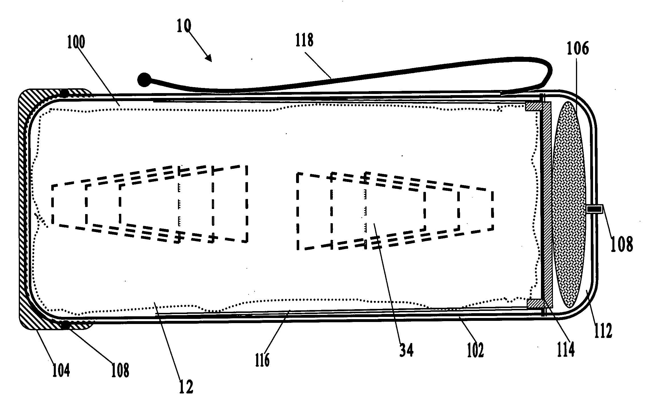
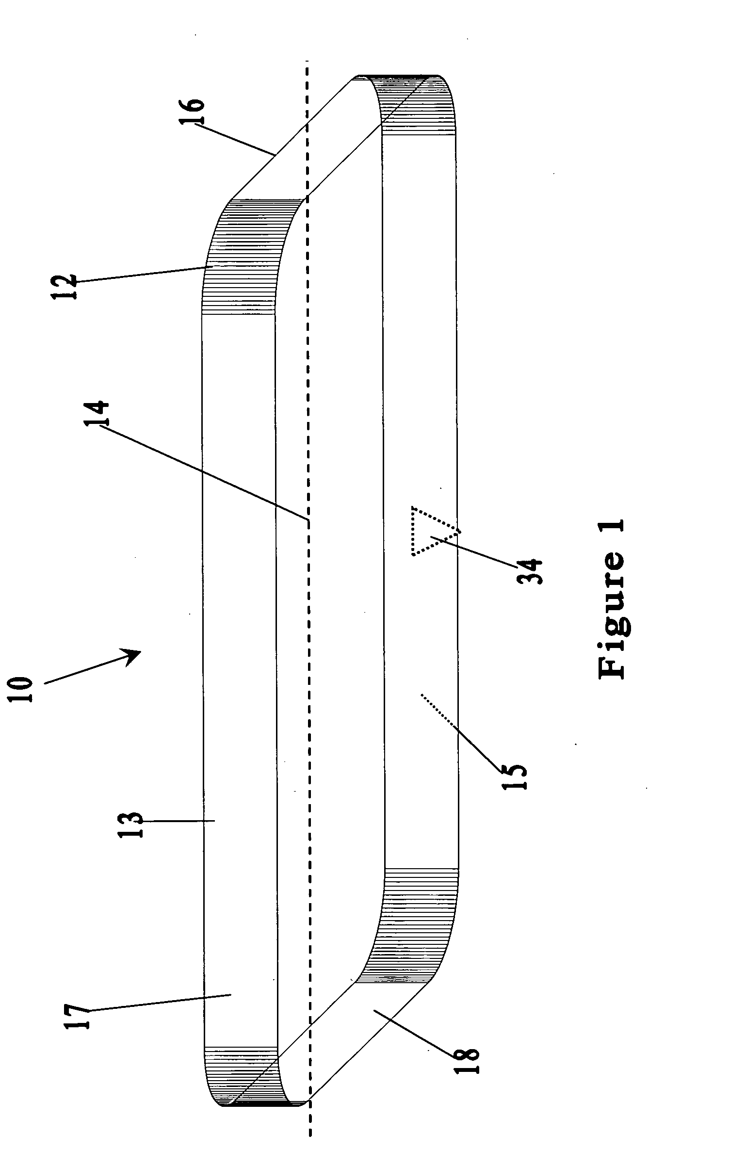
[0037]With reference to the drawings wherein like numerals represent like parts throughout the several figures, a deployable signaling device in accordance with the present invention is generally designated by the numeral 10.

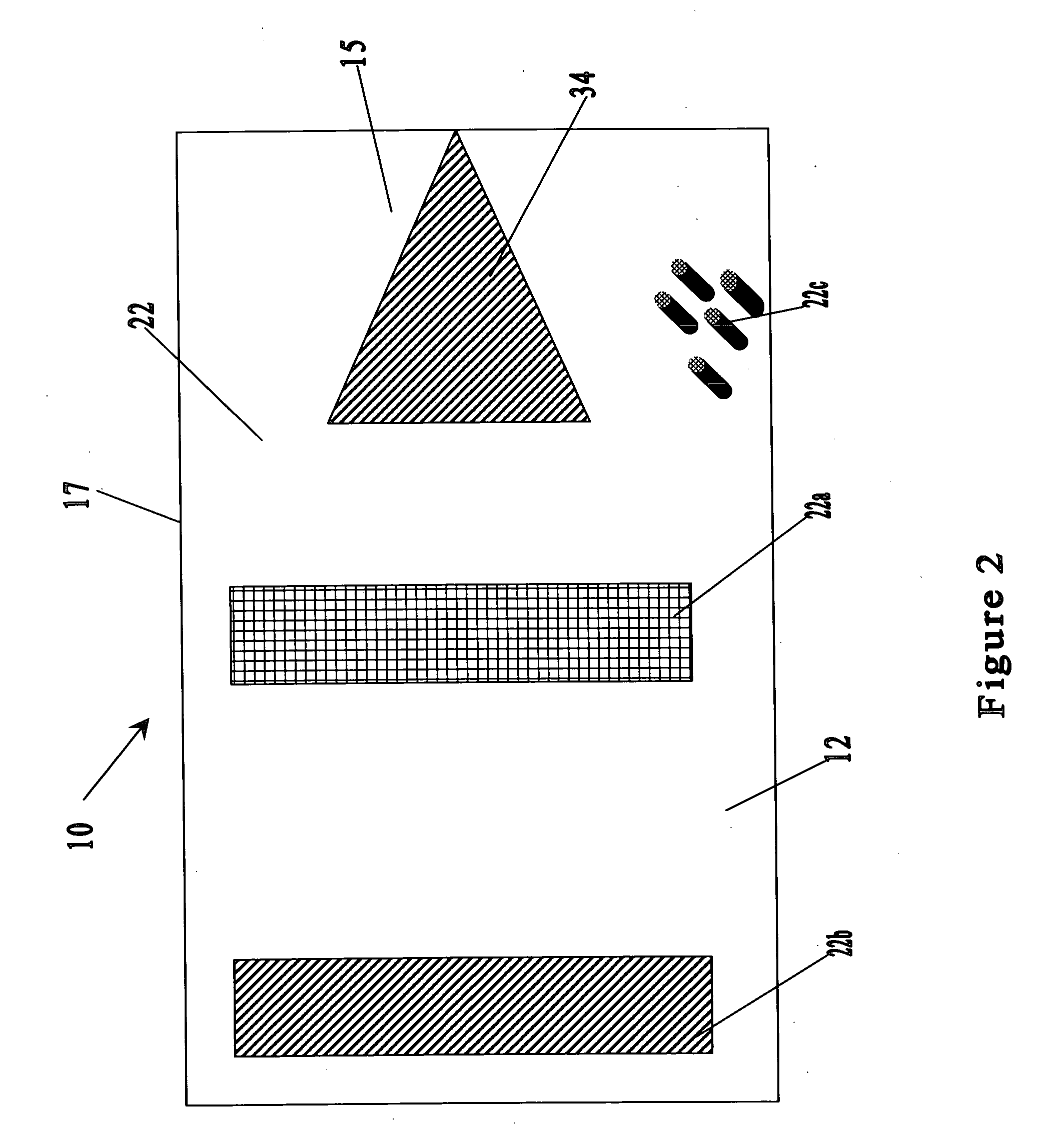
[0038]In one embodiment of the present invention, as shown in FIG. 1, the deployable signaling device 10 includes a deployable member 12 having, an upper surface 13, a lower surface 15, a border area 17, a center axis 14, a remote end 16, an attachable end 18, and an associated directional biasing element 34. In one embodiment of the present invention, the directional biasing elements 34 is associated with the lower surface 15.

[0039]The deployable member 12, in one embodiment of the present invention, may included material, or may be associated with materials, which provide the desired advantageous electromagnetic interactive properties. For example, the deployable member 12 may include material, or may be associated with materials, which exhibit, or can be made...


PUM


Abstract

A deployable signaling device and method of use thereof which includes material with detectable properties such that it can be distinguished from a background when deployed in various environments. Such detectable properties may include visible detection, detection by hyperspectral imaging sensors, radio wave detection, and/or detection other electromagnetic differentiation from the background in which the material is associated or adjacent to. In one preferred form, the selectively detectable material has an deployable shape having a plurality of directional biasing elements associated with said material.

Description

[0001]This application claims the benefit of U.S. Provisional Applications No. 60 / 878,842 filed Jan. 5, 2007 which is incorporated herein by reference in its entirety.FIELD OF THE INVENTION[0002]The invention generally relates to passive and / or active rescue or locational signaling devices for use in terrestrial, aquatic, and other desired environments. In particular, the invention relates to a device that can be observed and / or detected at a distance and a method of use thereof.BACKGROUND OF THE INVENTION[0003]The use of signaling devices is a time honored practice in both military and civilian based endeavors. In particular, over the centuries, maritime, aviation, and terrestrial expeditions have carried various items intended to enhance their detection and subsequent recovery in the event of an experienced emergency. Such things as smoke generating devices, dyes, flares, and radio broadcasting equipment have all been standard components of emergency and signaling equipment for de...

Claims


Application Information

Patent Timeline
Patent Type & Authority Applications(United States)
IPC IPC(8): G08B5/00
CPCG08B5/002Y10S116/08
Inventor HATFIELD, THOMAS A.
Owner HATFIELD THOMAS ANGELL
Why Eureka
Try Eureka