Laser net shape manufacturing using an adaptive toolpath deposition method

a toolpath deposition and tooling technology, applied in the direction of manufacturing tools, soldering devices, turbines, etc., can solve the problems of difficult replacement or repair of the blade portion of the blisk or the turbine blade, the final product is expensive to produce, and the entire blisk or the entire blisk is rejected and scrapped,

Active Publication Date: 2008-07-31
GENERAL ELECTRIC CO
View PDF6 Cites 74 Cited by
  • Summary
  • Abstract
  • Description
  • Claims
  • Application Information

AI Technical Summary

Problems solved by technology

The final product is expensive to produce, as it requires extensive high-precision machining operations.
An error in machining even one of the blades may result in rejection and scrapping of the entire BLISK or an expensive and time consuming repair.
Replacement or repair of a damaged blade portion of the BLISK or turbine blade presents a difficult problem with this cast and machine or forge and machine approach.
If all or a portion of a blade breaks off from impact of a foreign body during operation, for example, the BLISK becomes unbalanced.
However, such an approach is both expensive and may resu...

Method used


Image

  • Laser net shape manufacturing using an adaptive toolpath deposition method
  • Laser net shape manufacturing using an adaptive toolpath deposition method
  • Laser net shape manufacturing using an adaptive toolpath deposition method

Examples


Embodiment Construction

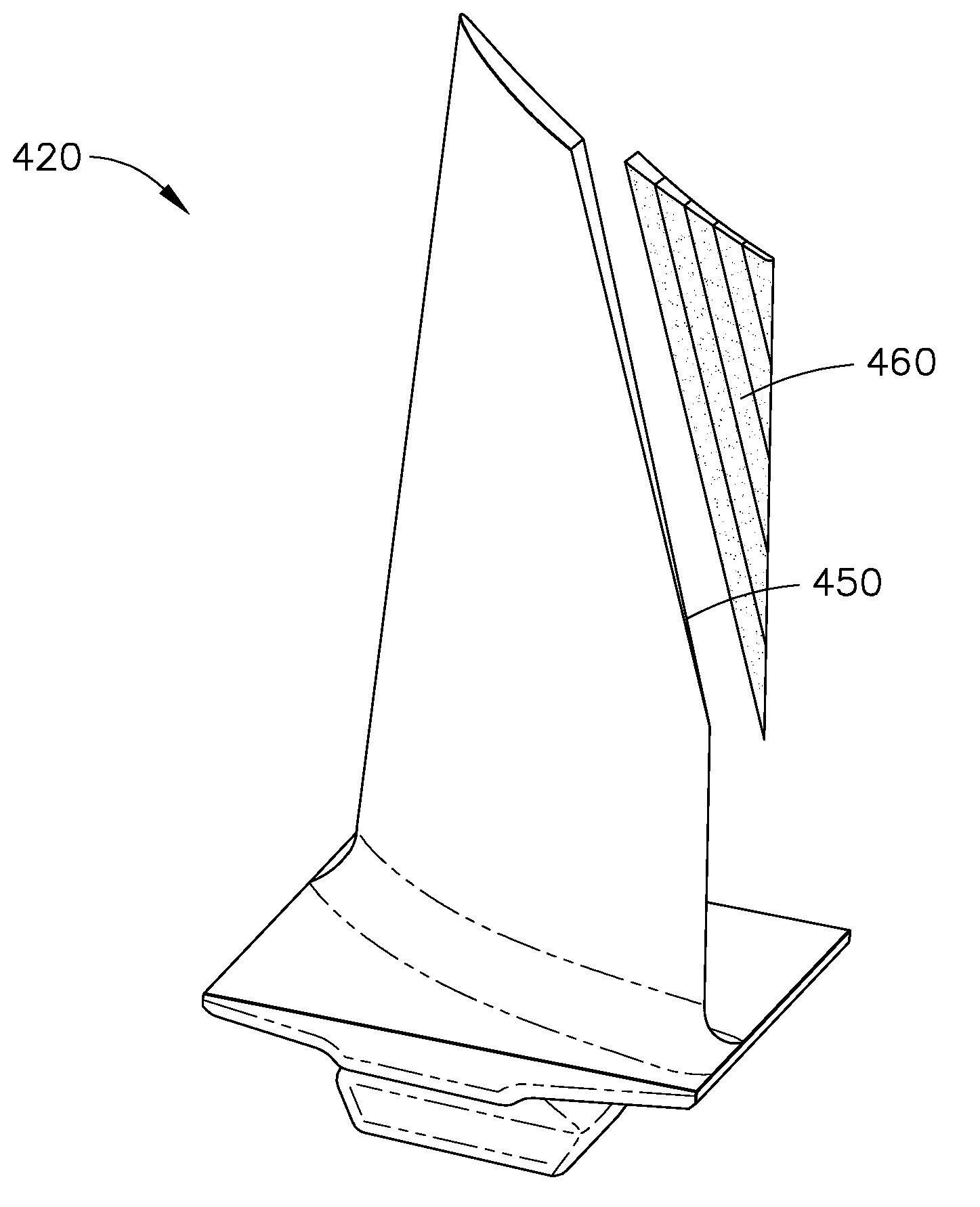
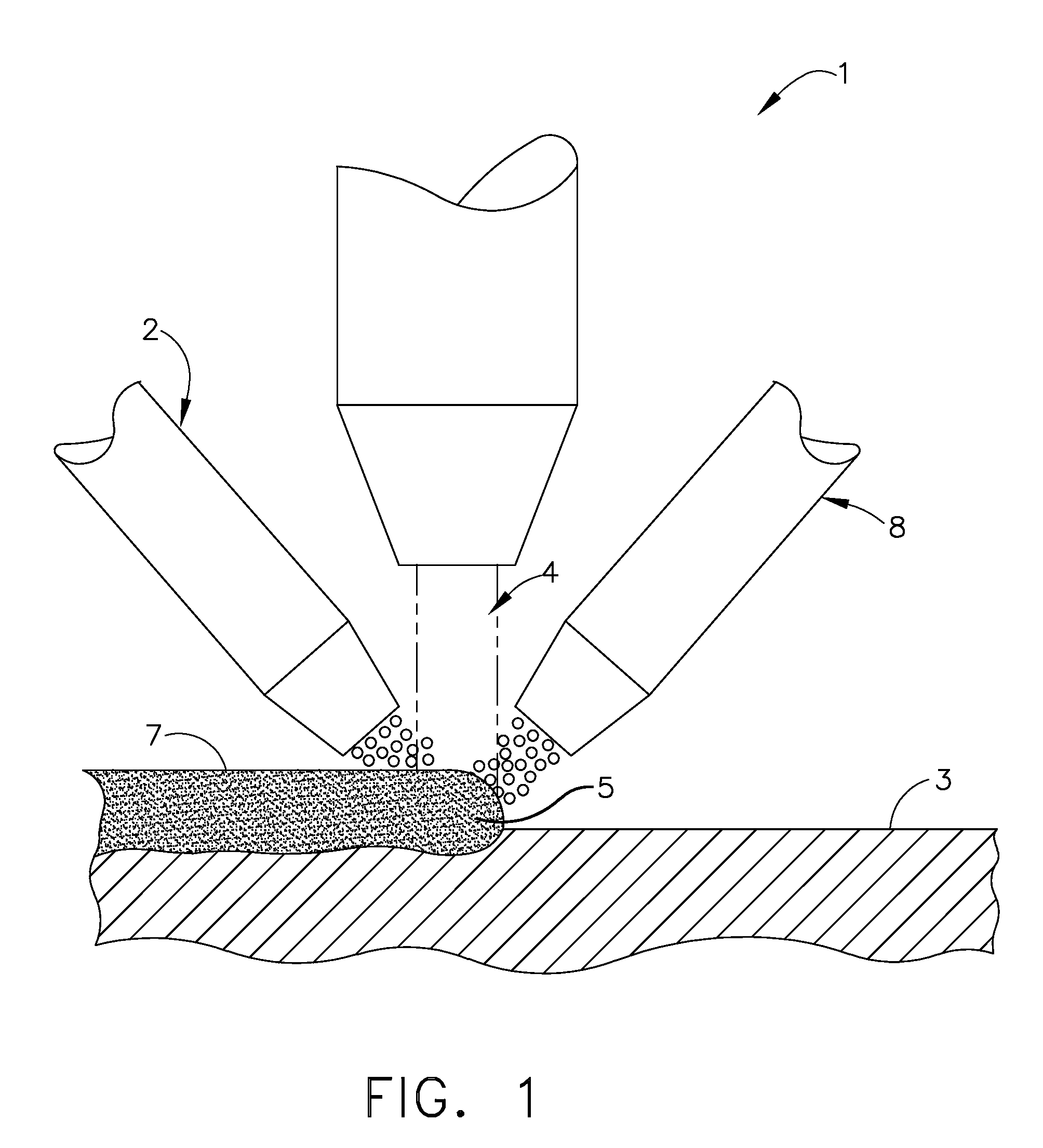
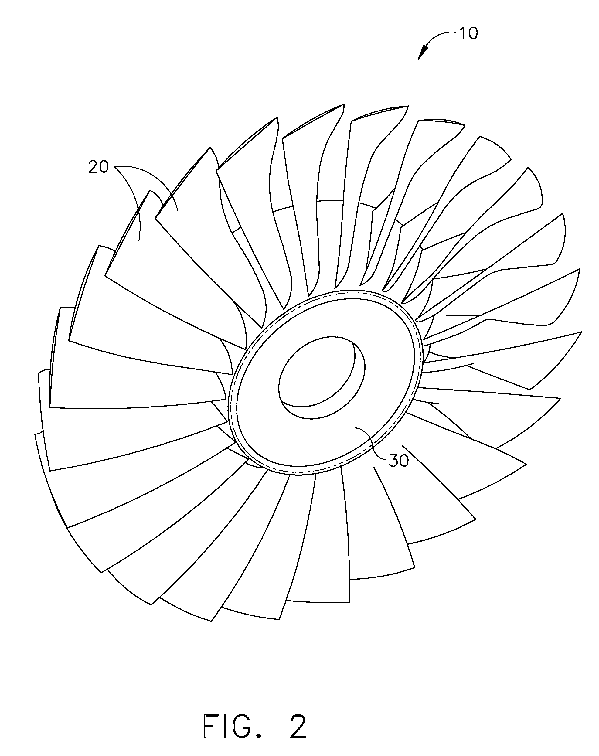
[0022]The present invention provides a Laser Net Shape Manufacturing (LNSM) method for fabricating and repairing articles such BLISKS, compressor blades, turbine blades, and compressor components that solves the problems associated with the prior art. The LNSM technique is based on laser cladding metal powders, wherein a laser is used to create a 3D geometry by precisely cladding thin layers of powder material on a base substrate using an adaptive toolpath deposition method. The adaptive toolpath method includes providing a predetermined variable bead width within a deposited layer. The base substrate may be a BLISK surface, such as BLISK compressor disk or a BLISK blade edge. Although specific embodiments discussed below are directed to BLISKS, the invention is equally applicable to the LNSM of other parts, including a variety of turbine parts including compressor blades and turbine blades.

[0023]To form a shaped deposit by LNSM, the dimensions and overall geometry of the part or re...


PUM

PropertyMeasurementUnit
Lengthaaaaaaaaaa
Lengthaaaaaaaaaa
Fractionaaaaaaaaaa

Abstract

A method is disclosed for laser cladding a substrate, comprising providing the substrate; depositing a first determined variable bead width of a material along a toolpath upon the substrate; depositing a second adjacent determined variable bead width of a material along the toolpath which overlaps the first determined variable bead width of deposited material; continuing to deposit a plurality of overlapping predetermined adjacent variable bead widths of a material until a first material layer is complete; forming a second material layer by depositing a plurality of overlapping predetermined variable bead widths of a material on top of the first material layer; and continuing to deposit material layers on top of deposited material layers until the cladding is complete; wherein the variable bead width of the deposited material is controlled by a computer having a plurality of input parameters to maintain an approximately constant percent of bead width overlap.

Description

FIELD OF THE INVENTION[0001]This invention relates to a manufacture and repair procedure for a part, for example a turbine component such as a bladed disk (BLISK), compressor blade, or turbine blade.BACKGROUND OF THE INVENTION[0002]An aircraft gas turbine engine or jet engine draws in and compresses air with an axial flow compressor, mixes the compressed air with fuel, burns the mixture, and expels the combustion gases through an axial flow turbine to power a compressor. The compressor includes a disk with blades projecting from its periphery. The disk turns rapidly on a shaft, and the curved blades draw in and compress air.[0003]In current manufacturing practice, the compressor is made by forging the compressor disk as a single piece with slots at the periphery. The compressor blades are individually cast or forged to shape with a root section termed a dovetail that fits into slots formed in the disk. Assembly is completed by sliding the dovetail sections of the blades into the slo...

Claims


Application Information

Patent Timeline
IPC IPC(8): B29C47/00
CPCB22F3/1055B22F5/04B23K2201/001B23P6/007B23K35/3033B23K26/345B23K35/3053B23K35/325B23K35/0244C23C24/106B23K35/3046B23K26/342B23K2101/001Y02P10/25B22F10/66B22F10/36B22F10/25B22F12/53B22F10/80F01D5/005F01D5/02F01D5/147F04D29/388F05D2220/30F05D2230/31F05D2230/80
Inventor QI, HUANSINGH, PRABHJOTAZER, MAGDI NAIM
Owner GENERAL ELECTRIC CO
Why Eureka
Try Eureka