Keypad and keypad assembly

a keypad and assembly technology, applied in the field of keypad assembly, can solve the problems of inconvenience for users, easy portability, and difficulty in integrating the unique input keys of each device, and achieve the effect of improving visibility and efficient illumination structur

Inactive Publication Date: 2008-07-31
SAMSUNG ELECTRONICS CO LTD
View PDF7 Cites 90 Cited by
  • Summary
  • Abstract
  • Description
  • Claims
  • Application Information

AI Technical Summary

Benefits of technology

[0012]An aspect of the present invention is to address at least the above problems and / or disadvantages. Accordingly, an aspect of the present invention is to provide a keypad and a keypad assembly having an efficient illumination structure and improved visibility.

Problems solved by technology

As various portable devices have been released to the market, easy portability has emerged as an important issue.
When various devices are integrated into a portable wireless terminal, it is a difficult challenge to integrate unique input keys of each of the devices into a keypad assembly of the portable wireless terminal.
Although such a problem has been solved by expressing a plurality of symbols on each of the key tops or using software, this solution causes inconvenience to users due to low visibility.
However, the conventional keypad assembly using the electronic paper has problems as follows.
First, the light emitting device is disposed between the housing and the transparent keypad, making it difficult to prevent leakage of light.
In particular, when a print is made on the transparent keypad, the luminance of light that is incident to the electronic paper degrades greatly, causing low visibility.
Second, when a user presses the actuator button, a transformed portion of the electronic portion directly presses a corresponding switch, resulting in a poor sense of clicking.
Third, a large number of light emitting devices for uniformly and brightly illuminating the electronic paper increases power consumption and manufacturing cost.

Method used


Image

  • Keypad and keypad assembly
  • Keypad and keypad assembly
  • Keypad and keypad assembly

Examples


Embodiment Construction

[0027]The matters defined in the description such as a detailed construction and elements are provided to assist in a understanding of exemplary embodiments of the invention. Accordingly, those of ordinary skill in the art will recognize that various changes and modifications of the embodiments described herein can be made without departing from the scope and spirit of the invention. Also, descriptions of well-known functions and constructions are omitted for clarity and conciseness.

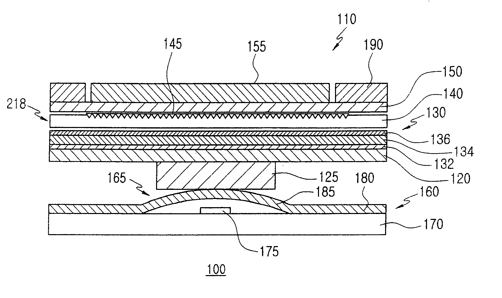
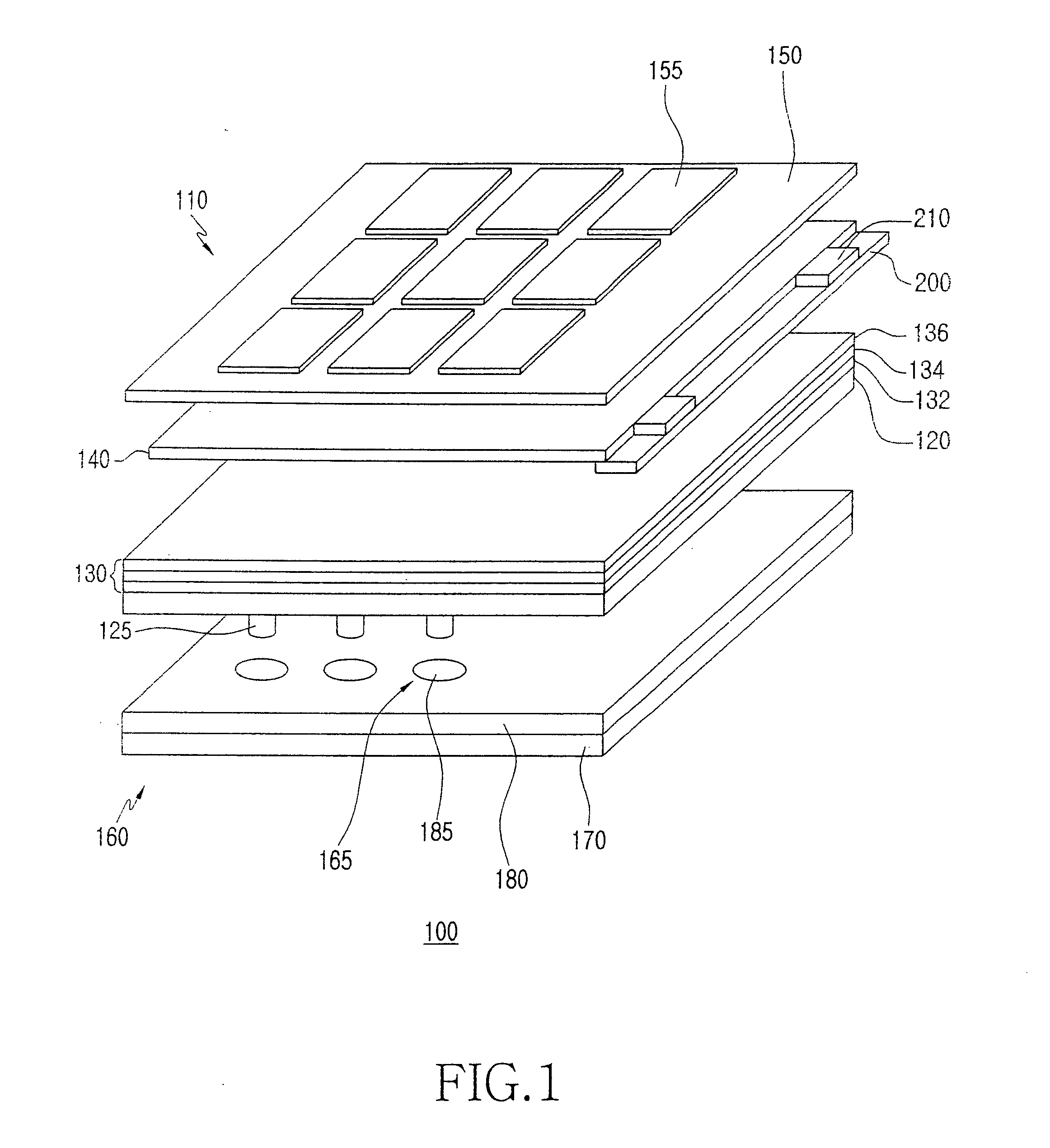
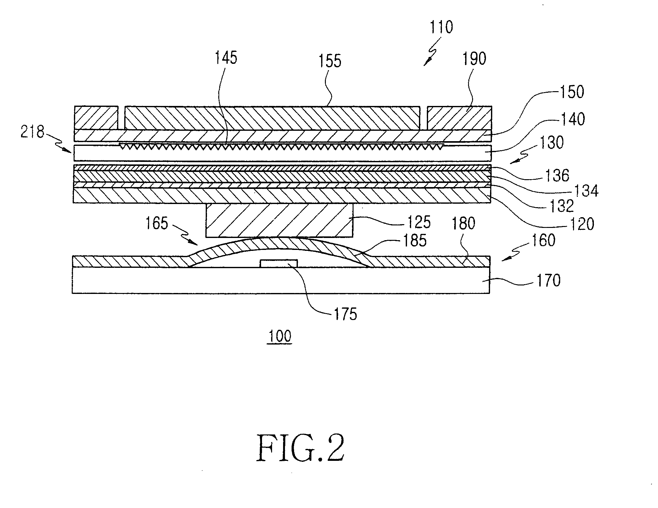
[0028]FIG. 1 is a perspective view of a keypad assembly 100 according to an exemplary embodiment of the present invention, and FIG. 2 is a cross-sectional view of a portion of the keypad assembly 100 illustrated in FIG. 1. The keypad assembly 100 can be mounted in a portable wireless terminal and includes a keypad 110 and a switch board 160 that are disposed to face each other, a second Printed Circuit Board (PCB) 200, and at least one light emitting device 210.

[0029]The keypad 110 includes an upper elas...


PUM


Abstract

A keypad and a keypad assembly are disclosed. The keypad includes a light guide layer, inside which light travels and electronic paper which is illuminated by light irradiated from the light guide layer and expresses at least one symbol by reflection of the light.

Description

CLAIM OF PRIORITY [0001]This application claims the benefit of the earlier filing date, under 35 U.S.C. §119(a), to that patent application filed in the Korean Intellectual Property Office on Jan. 31, 2007 and assigned Serial No. 2007-9983, the entire disclosure of which is hereby incorporated by reference.BACKGROUND OF THE INVENTION [0002]1. Field of the Invention[0003]The present invention relates to a keypad assembly for a portable device, and in particular, to a keypad assembly using a light guide layer and electronic paper.[0004]2. Description of the Related Art[0005]As various portable devices have been released to the market, easy portability has emerged as an important issue. Moreover, with the development of a digital convergence technique for converging a plurality of portable devices into one, various functions are integrated into a portable wireless terminal. For example, a number of portable wireless terminals having an MP3 player, a digital camera, and a game console i...

Claims


Application Information

Patent Timeline
Patent Type & Authority Applications(United States)
IPC IPC(8): H01H9/00H03M11/00
CPCH01H13/83H01H2209/074H01H2219/0023H01H2219/062H01H2219/056H01H2219/06H01H2219/014A43C15/063A43C15/10
Inventor JUNG, SUN-TAELEE, JOO-HOON
Owner SAMSUNG ELECTRONICS CO LTD
Why Eureka
Try Eureka