Lenticular airship

a technology of lenticular airships and airships, applied in hybrid airships, process and machine control, instruments, etc., can solve the problems of airships to adverse aeronautic effects, airships to and airships that are streamlined airships, in particular, may experience adverse effects based on aerodynamic forces

Inactive Publication Date: 2008-07-31
LTA
View PDF70 Cites 59 Cited by
  • Summary
  • Abstract
  • Description
  • Claims
  • Application Information

AI Technical Summary

Benefits of technology

[0016]In yet another aspect, the present disclosure is directed to a flight control system for a lighter-than-air airship. The system may include one or more operator controls configured to receive operator input, a horizontal control surface associated with a horizontal stabilizing member, a vertical control surface associated with a vertical stabilizing member, a processor configured to receive an input signal from the operator controls and generate a control signal according to the input signal, and five propulsion assemblies. A first of the five propulsion assemblies may be operably coupled to a support structure associated with the airship and located at a first location on a periphery associated with the airship, a second of the five propulsion assemblies may be operably coupled to the sup

Problems solved by technology

Navigation of such an airship has proven to be difficult, mainly due to wind currents and lack of propulsion units for directing the balloon.
The airships are typically streamlined in a blimp- or zeppelin-like shape, which, while providing reduced drag, may subject the airship to adverse aeronautic effects (e.g., weather cocking).
Hull design and streamlining of airships may provide additional lift once the airship is underway, however, previously designed streamlined airships, in particular, may experience adverse effects based on aerodynamic forces because of such hull designs.
W

Method used


Image

  • Lenticular airship
  • Lenticular airship
  • Lenticular airship

Examples


Embodiment Construction

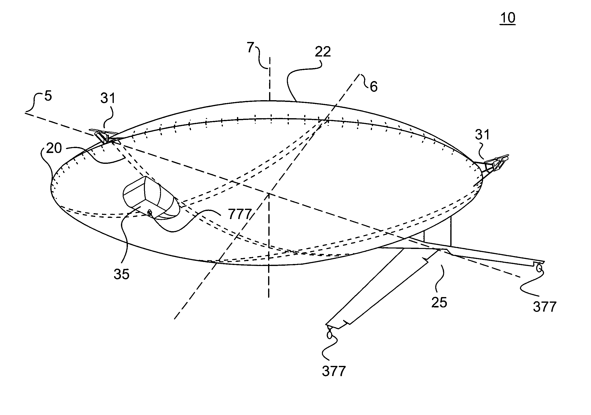
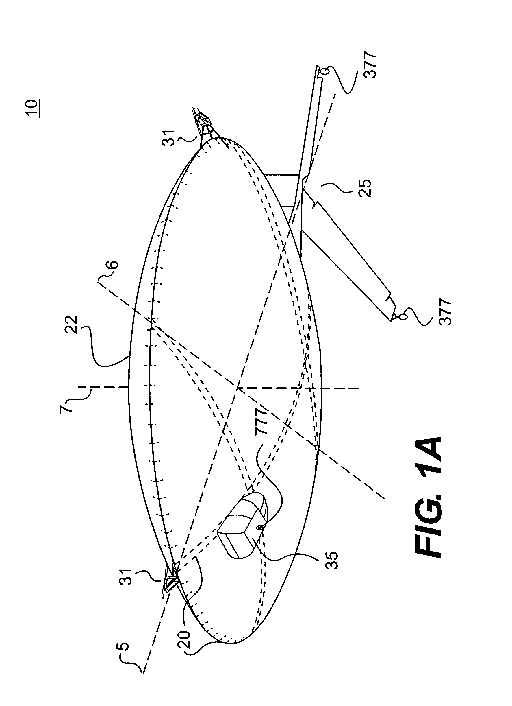
[0035]FIG. 1A illustrates one exemplary embodiment of a lenticular airship (LA) 10. LA 10 may be configured for VTOL as well as navigation in three dimensions (e.g., X, Y, and Z planes). To facilitate such flight, LA 10 may include a support structure 20, a hull 22, an empennage assembly 25, rear landing gear assemblies 377, a propulsion system including propulsion assemblies 31, a gondola 35, one or more computers 600 (see, e.g., FIG. 7), and / or a front landing gear assembly 777. Throughout this discussion of various embodiments, the terms “airship” and airship may be used interchangeably to refer to various embodiments of LA 10. Further, the terms “front” and / or “fore” will be used to refer to areas within a hemisphere section of LA 10 closest to forward travel, and the term “rear” and / or “aft” will be used to refer to areas within a hemisphere section of LA 10 closest to the opposite direction of travel. Moreover, the term “tail” will be used to refer to a rear most point associa...


PUM


Abstract

An airship may include a hull substantially shaped as an oblate spheroid, one or more frame members defining a support structure, wherein the support structure forms at least a partial support for the hull, at least one horizontal stabilizing member operably coupled to a lower surface of the airship, and at least one horizontal stabilizing member having a first end and a second end. The at least one horizontal stabilizing member may define an anhedral configuration. The airship may also include a vertical stabilizing member having a first end pivotally coupled to the airship and a second end oriented to remain below an upper surface of the airship. The vertical stabilizing member may be configured to pivot within a vertical plane, and the first end of the vertical stabilizing member and the first end of the at least one horizontal stabilizing member may be operably coupled to one another.

Description

RELATED APPLICATIONS[0001]This application claims priority under 35 U.S.C. § 119 to U.S. Provisional Application No. 60 / 852,971, filed Oct. 20, 2006; U.S. Provisional Application No. 60 / 877,667, filed Dec. 29, 2006; and U.S. Provisional Application No. 60 / 907,549, filed Apr. 6, 2007. The subject matter of these U.S. Provisional Applications is hereby incorporated by reference.TECHNICAL FIELD[0002]The present disclosure relates to lenticular airship. More particularly, the disclosure relates to a lenticular airship.BACKGROUND INFORMATION[0003]Aerostatic lighter-than-air airships have seen substantial use since 1783 following the first successful manned flight of the Montgolfier brothers' hot air balloon. Numerous improvements have been made since that time, but the design and concept of manned hot air balloons remains substantially similar. Such designs may include a gondola for carrying a pilot and passengers, a heating device (e.g., a propane torch), and a large envelope or bag aff...

Claims


Application Information

Patent Timeline
IPC IPC(8): B64B1/06B64B1/08B64B1/12B64B1/24G05D1/08
CPCB64B1/06B64B1/10B64B1/12B64B2201/00B64B1/34B64C2201/00B64B1/30B64U10/00
Inventor BALASKOVIC, PIERRE
Owner LTA
Why Eureka
Try Eureka