Single Slotted Flap With Sliding Deflector Flap and Lowerable Spoiler

a single-slotted, deflector technology, applied in the direction of air braking surface, wing adjustment, weight reduction, etc., can solve the problems of increased noise level, increased air-flow speed, and reduced lift generated by high-lift devices correspondingly, so as to simplify the construction of high-lift devices and improve the effect of high-lift devices

Inactive Publication Date: 2008-07-31
AIRBUS OPERATIONS GMBH
View PDF14 Cites 11 Cited by
  • Summary
  • Abstract
  • Description
  • Claims
  • Application Information

AI Technical Summary

Benefits of technology

[0013]Among other thinks, it may be an object of the present invention to provide flexible adjustment of the lift characteristics of a wing element.

Problems solved by technology

This may result in the lift generated by the high lift devices being reduced correspondingly (pressure equalisation between the top and the underside) and in the noise level being increased (high air-flow speed in the slot).

Method used


Image

  • Single Slotted Flap With Sliding Deflector Flap and Lowerable Spoiler
  • Single Slotted Flap With Sliding Deflector Flap and Lowerable Spoiler

Examples


Embodiment Construction

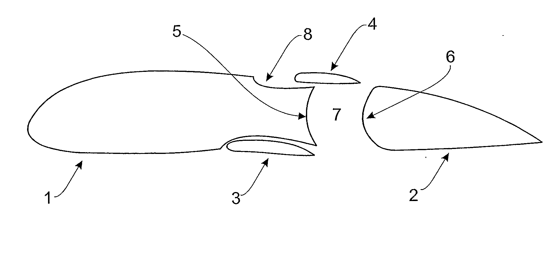
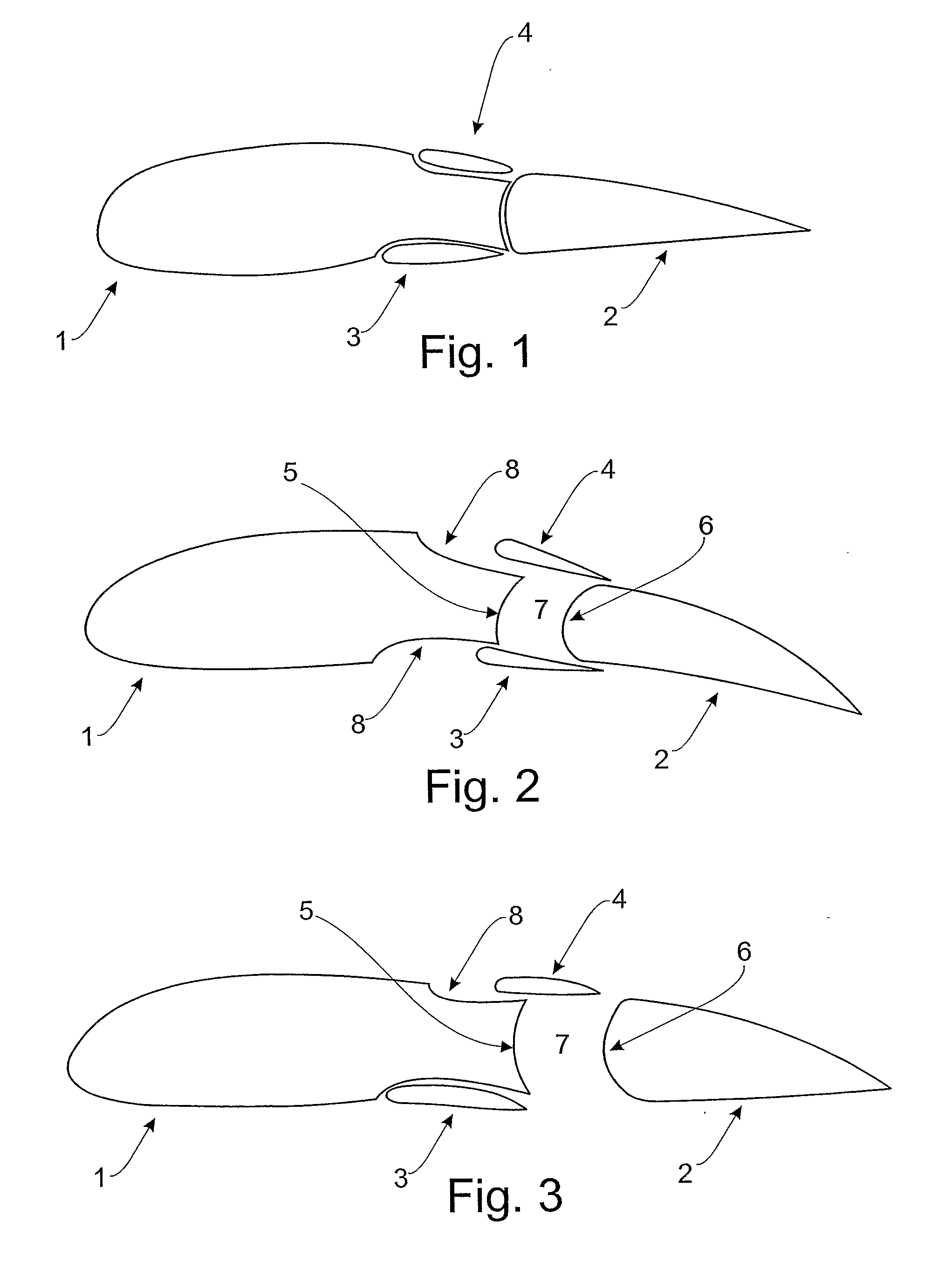
[0045]FIG. 1 shows a device for adjusting the lift characteristics of an aircraft, according to an exemplary embodiment of the invention.

[0046]The device comprises a wing element 1, a high lift device 2 and two slot covering devices 3, 4. The high lift device 2 is movably attached to the wing element 1. The slot covering devices 3, 4 are also movably attached to the wing element 1. The slot covering devices 3, 4 are designed so as to regulate the size of a slot 7 between the wing element 1 and the high lift device 2.

[0047]FIG. 1 shows the wing element 1 with the high lift device 2 retracted. This configuration is preferably used during cruising so as to keep the wing surface small and thus may be reduce resistance. The wing profile from FIG. 1 may be designed such that at a specified angle of attack the lift force is in equilibrium with the opposing weight force. In this way at constant altitude cruising with little resistance may be achieved. In this arrangement the slot covering d...


PUM


Abstract

The present invention relates to a device for adjusting the lift characteristics of an aircraft with a high lift device (2) that is movably attachable to a wing element (1) and that comprises at least one slot covering device (3; 4), wherein the at least one slot covering device (3; 4), is movably attachable to the wing element (1). The slot covering device (3; 4) is designed to regulate the size of a slot (7) between the wing element (1) and the high lift device (2).

Description

REFERENCE TO RELATED APPLICATIONS[0001]This application claims the benefit of the filing date of German Patent Application No. 10 2005 016 578.8 filed Apr. 11, 2005 and of U.S. Provisional Patent Application No. 60 / 670,201 filed Apr. 11, 2005, the disclosures of which applications are hereby incorporated herein by reference.FIELD OF THE INVENTION[0002]The present invention relates to a device and a method for adjusting lift characteristics, to a means of locomotion, and to the use of a device for adjusting lift characteristics in an aircraft.BACKGROUND OF THE INVENTION[0003]In order to attain a particular lift during slow flight, modern commercial aircraft require high lift devices during the takeoff and landing phases. During the takeoff phase high lift devices are used to generate a high coefficient of lift combined with little resistance and a low noise level. Likewise, these conditions apply during the landing phase, wherein in this case the low resistance plays a subordinate ro...

Claims


Application Information

Patent Timeline
Patent Type & Authority Applications(United States)
IPC IPC(8): B64C9/14
CPCB64C9/02B64C9/18Y02T50/44B64C2009/143B64C9/20Y02T50/40
Inventor BENDER, KLAUSBOETTGER, OLE
Owner AIRBUS OPERATIONS GMBH
Why Eureka
Try Eureka