Unlock instant, AI-driven research and patent intelligence for your innovation.
Piezoelectric thin-film resonator
Active Publication Date: 2008-07-31
MURATA MFG CO LTD
View PDF14 Cites 43 Cited by
Summary
Abstract
Description
Claims
Application Information
AI Technical Summary
This helps you quickly interpret patents by identifying the three key elements:
Problems solved by technology
Method used
Benefits of technology
Benefits of technology
[0011]To overcome the problems described above, preferred embodiments of the present invention provide a piezoelectric thin-film resonator which suppresses a spurious component having a short wavelength.
Problems solved by technology
When the planar shape of the vibration unit is square, standing waves occur between the opposing sides of the vibration unit, and therefore, a spurious component is generated.
However, the Q value of resonance is disadvantageously decreased.
In addition, if the vibration unit has a non-rectangular, irregular polygonal planar shape, it is difficult to reduce the size of the vibration unit.
However, a spurious component of the Lamb waves having a short wavelength cannot be suppressed.
Method used
Image
Click on the blue label to locate the original text in one second.
Reading with bidirectional positioning of images and text.
Examples
first preferred embodiment
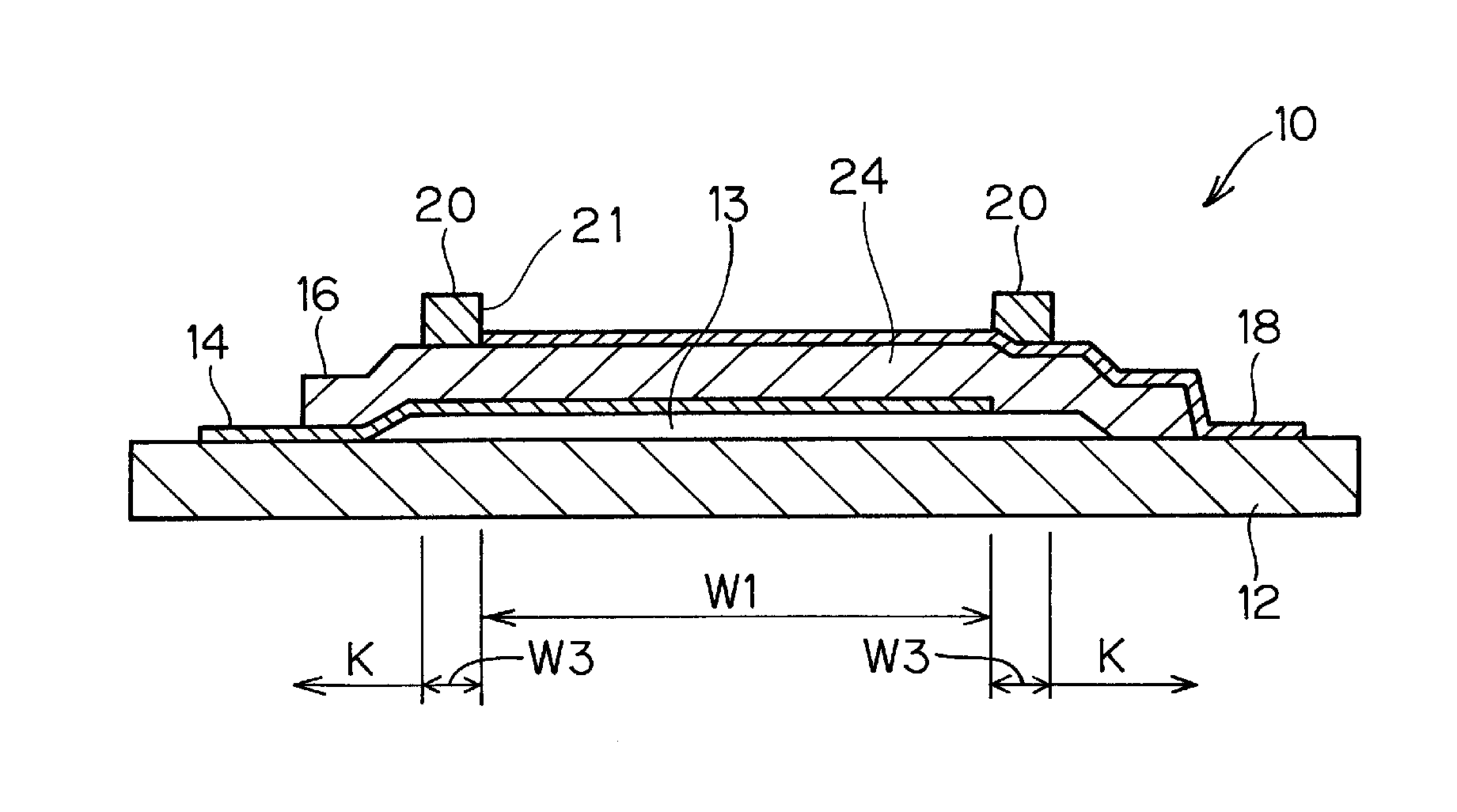
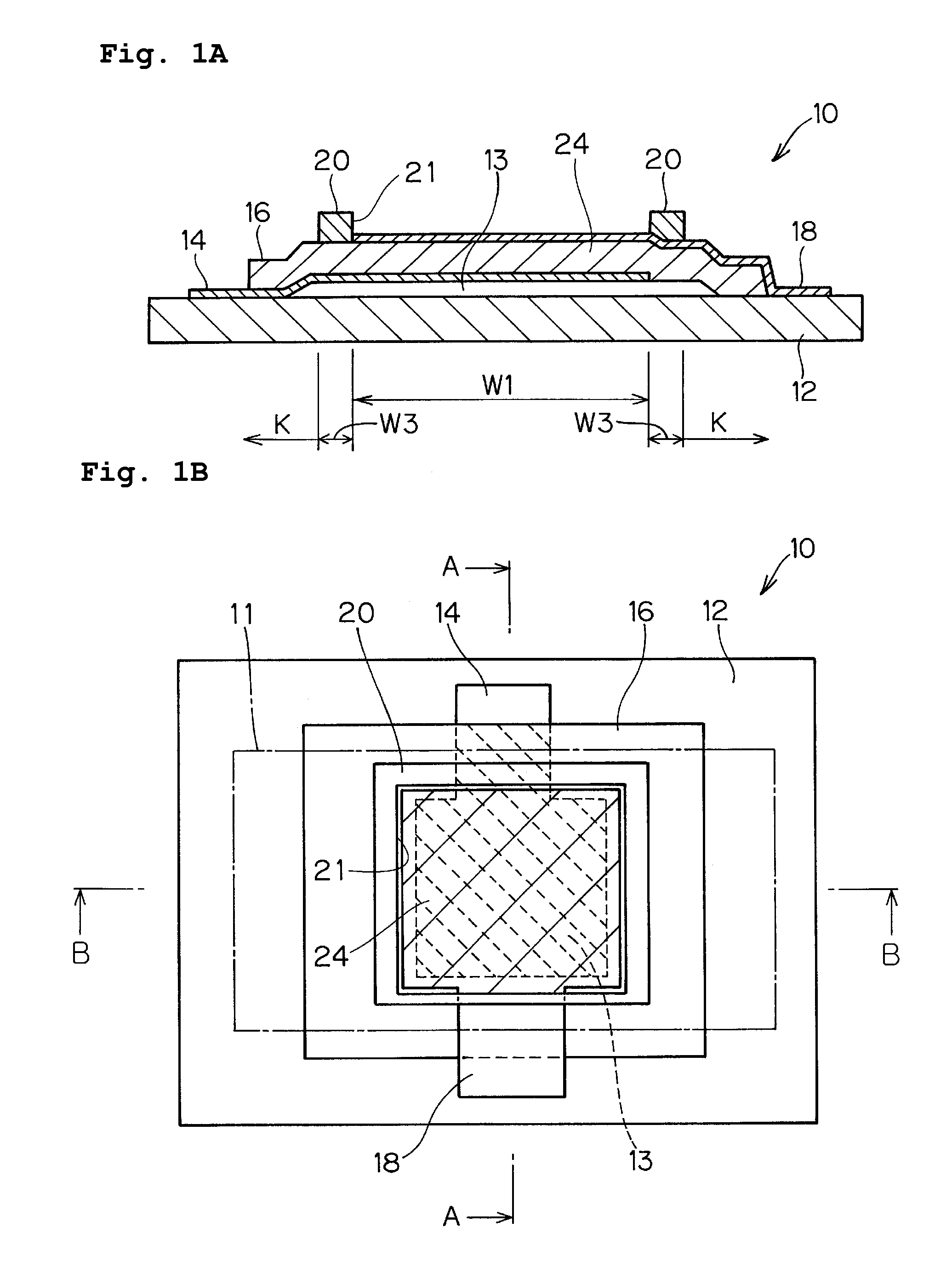
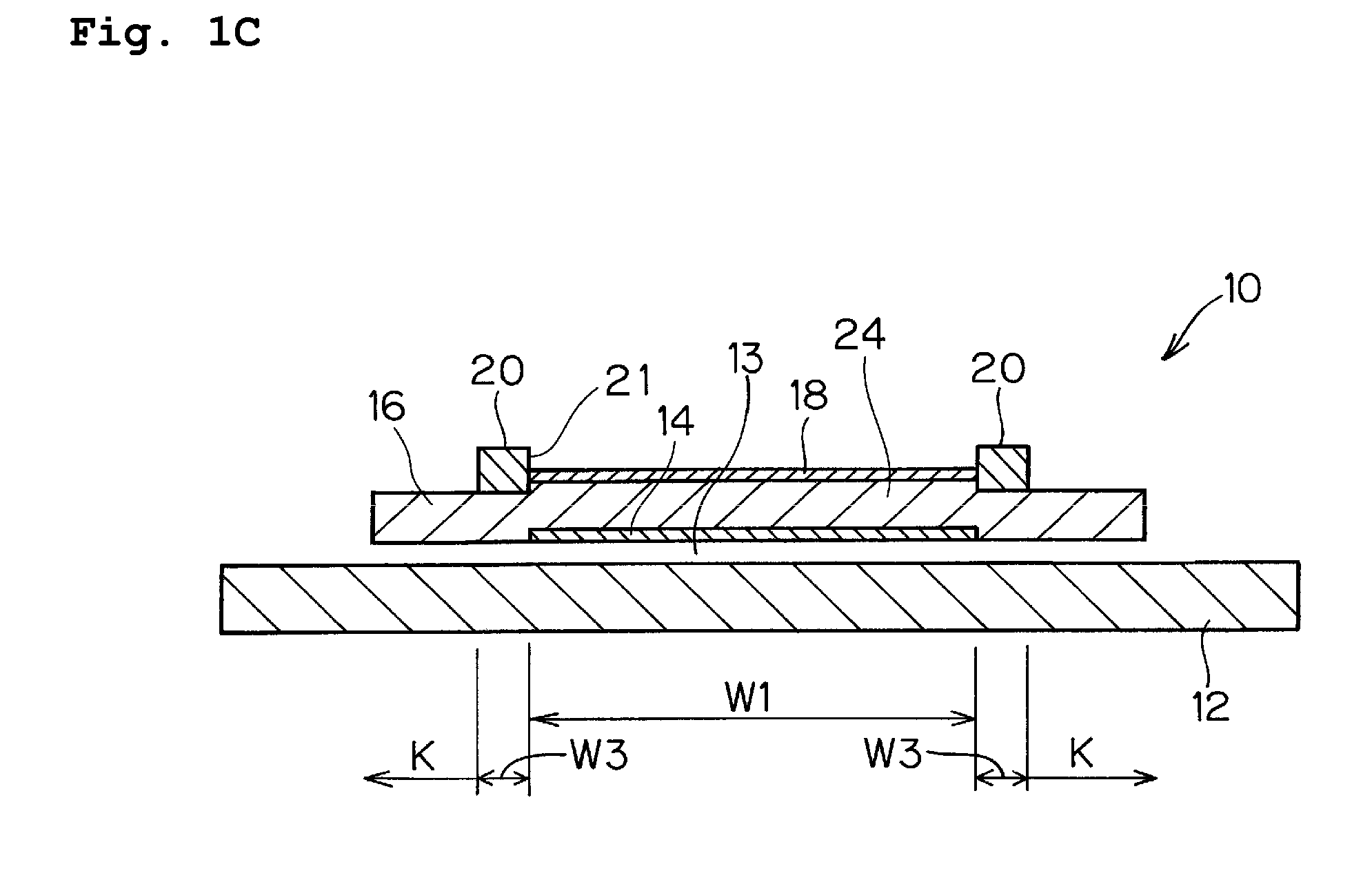
[0048]A piezoelectric resonator 10 according to a first preferred embodiment is described with reference to FIGS. 1A, 1B, 1C, and 2. FIG. 1B is a plan view. FIG. 1A is a cross-sectional view taken along a line A-A in FIG. 1B. FIG. 1C is a cross-sectional view taken along a line B-B in FIG. 1B.
[0049]As schematically shown in FIGS. 1A, 1B, and 1B, the piezoelectric resonator 10 includes a thin film unit provided on a substrate 12. That is, a lower electrode 14, a piezoelectric film 16, an upper electrode 18, and an additional film 20 are sequentially stacked on the substrate 12. The lower electrode 14 includes a portion supported by the substrate 12 and a portion raised above the substrate 12 with a gap 13 therebetween. A vibration unit 24 is provided on the raised portion. The vibration unit 24 includes the piezoelectric film 16 disposed between the lower electrode 14 and the upper electrode 18. As shown in FIG. 1B, the gap 13 is formed by disposing a sacrificial layer 11 on the subs...
second preferred embodiment
[0063]In a second preferred embodiment, the sizes and structures similar to those of the particular example of the first preferred embodiment are used except for the additional films 20. In the second preferred embodiment, the additional films 20 are made of SiO2 having a density of 2.2 g / cm3 and have thicknesses of about 200 nm, about 340 nm, about 350 nm, about 450 nm, about 520 nm, and about 530 nm.
[0064]FIG. 3 illustrates the impedance Smith charts of these piezoelectric resonators 10 including additional films 20 having these thicknesses.
[0065]A relationship between the A / B ratio and the degree of spurious suppression for the piezoelectric resonators 10 including additional films 20 having these thicknesses is shown in Table 4.
TABLE 4B: Density ×Degree ofA: Density × ThicknessThicknessSuppression ofofofSpuriousAdditional FilmElectrodeA / B RatioComponents4408890.5X7488890.8X7708890.9◯9908891.1◯1,1448891.2◯1,1668891.3X
[0066]As shown in Table 4, when the A / B ratio is in the range o...
third preferred embodiment
[0067]In a third preferred embodiment, the sizes and structures similar to those of the particular example of the first preferred embodiment are used except for the additional films 20. In the third preferred embodiment, the additional films 20 are made of Al having a density of 2.7 g / cm3 and have thicknesses of about 310 nm, about 320 nm, about 510 nm, and about 520 nm.
[0068]A relationship between the A / B ratio and the degree of spurious suppression for the piezoelectric resonators 10 including additional films 20 having these thicknesses is shown in Table 5.
TABLE 5B: Density ×Degree ofA: Density × ThicknessThicknessSuppression ofofofSpuriousAdditional FilmElectrodeA / B RatioComponents6828890.8X8648891.0◯1,3778891.5◯1,4048891.6X
[0069]As shown in Table 5, when the A / B ratio is in the range of about 1.0 to about 1.5, the spurious components are suppressed.
PUM
Abstract
In a piezoelectric resonator, a portion of a thin film unit is supported by a substrate. A portion of the thin film unit acoustically isolated from the substrate includes a) a vibration unit and b) an additional film. The vibration unit includes a piezoelectric film sandwiched between a pair of electrodes. The piezoelectric film is overlapped with the pair of electrodes in plan view. The additional film is disposed on one of the piezoelectric film and the electrodes so as to extend along at least a portion of the periphery of the vibration unit. When x (MN·second / m3) denotes an acoustic impedance of the additional film defined by the square root of the product of the density and Young's modulus, A denotes the product of the density and the thickness of the additional film, B denotes the product of the densities and the thicknesses of the electrodes, and y=A / B, the following conditional expressions are satisfied:In the range of 9.0≦x<44.0,0.0092·x+0.88≦y<0.067·x+0.60 (1a)In the range of 44.0≦x<79.0,−0.0035·x+1.45≦y<0.015·x+2.9. (1b)
Description
BACKGROUND OF THE INVENTION[0001]1. Field of the Invention[0002]The present invention relates to a piezoelectric thin-film resonator.[0003]2. Description of the Related Art[0004]Piezoelectric thin film resonators include a thin film unit disposed on a substrate. The thin film unit has a piezoelectric film sandwiched by upper and lower electrodes. An overlapping portion of the upper and lower electrodes functions as a vibration unit, which is acoustically isolated from the substrate. When an alternating voltage is applied to the vibration unit, the vibration unit operates in a thickness extensional vibration mode at a frequency for which the thickness of the vibration unit is approximately equal to a half wavelength. At the same time, Lamb waves are excited so as to propagate in a planar direction of the piezoelectric film. When the planar shape of the vibration unit is square, standing waves occur between the opposing sides of the vibration unit, and therefore, a spurious component ...
Claims
Application Information
Patent Timeline
Application Date:The date an application was filed.
Publication Date:The date a patent or application was officially published.
First Publication Date:The earliest publication date of a patent with the same application number.
Issue Date:Publication date of the patent grant document.
PCT Entry Date:The Entry date of PCT National Phase.
Estimated Expiry Date:The statutory expiry date of a patent right according to the Patent Law, and it is the longest term of protection that the patent right can achieve without the termination of the patent right due to other reasons(Term extension factor has been taken into account ).
Invalid Date:Actual expiry date is based on effective date or publication date of legal transaction data of invalid patent.

