
Battery montoring apparatus and daisy chain interface suitable for use in a battery monitoring apparatus

Active Publication Date: 2008-07-31
ANALOG DEVICES INC
View PDF11 Cites 71 Cited by
  • Summary
  • Abstract
  • Description
  • Claims
  • Application Information

AI Technical Summary

Benefits of technology

[0004]Rather than use a single monitoring apparatus to monitor the entirety of the battery stack, the battery stack can be broken down into subunits and each of these subunits can then be monitored by an individual battery monitor. The potential difference spanning across each subunit is much reduced and as a result relatively inexpensive semiconductor fabrication processes can be used to fabricate integrated circuits capable of operating with the limited potential difference existing across the subunit within the battery stack.
[0005]Whilst dividing the monitoring task across a plurality of battery monitors reduces the voltage range that each monitor has to operate over, it is still necessary to communicate the output from the battery monitor to a data processing system. In order to reduce cost, for example by avoiding the need for potential dividers between the battery monitor and the individual cells it is desirable to allow the power rails of a given battery monitor to approach or equal the voltages occurring around the associated cells that are being monitored. Thus, for a first battery monitor its “negative” supply rail may be at 0 volts with respect to a ground voltage and its “positive” supply rail may be at, say, +25 volts. Consequently the second battery monitor supplies may float with respect to ground such that its “negative” supply rail is at +25 volts and its “positive” supply rail is a +50 volts. This pattern can continue and hence it can be seen that the outputs supply voltage and consequently the potentials at of some of the monitoring devices may occur as very high voltages indeed. The outputs can, of course, be coupled to other data processing systems by use of isolators, such as opto isolators, but these increase the overall system costs still further.

Problems solved by technology

The outputs can, of course, be coupled to other data processing systems by use of isolators, such as opto isolators, but these increase the overall system costs still further.

Method used


Image

  • Battery montoring apparatus and daisy chain interface suitable for use in a battery monitoring apparatus
  • Battery montoring apparatus and daisy chain interface suitable for use in a battery monitoring apparatus
  • Battery montoring apparatus and daisy chain interface suitable for use in a battery monitoring apparatus

Examples


Embodiment Construction

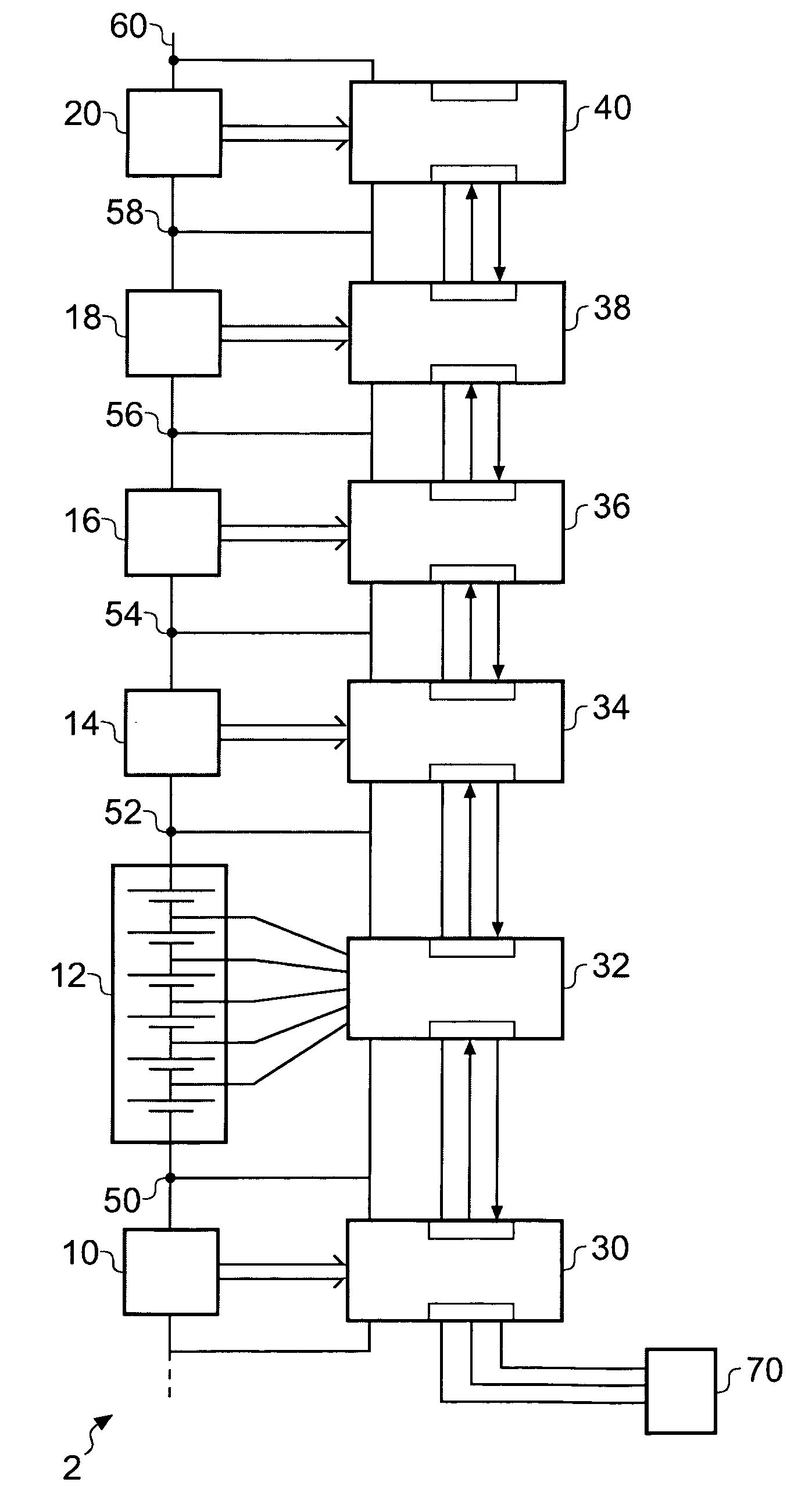
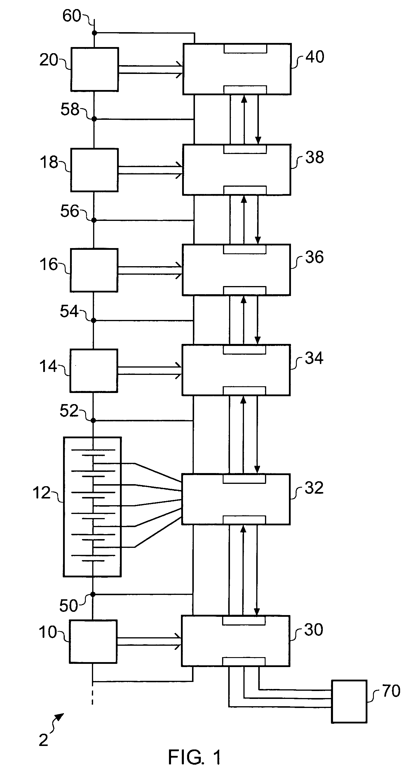
[0015]FIG. 1 schematically shows a battery stack, generally designated 2, comprising first, second, third, fourth, fifth and sixth groups of cells 10, 12, 14, 16, 18 and 20 respectively. Each of the groups of cells is nominally identical, and for clarity, only the individual cells within the second group 12 are individually drawn. In this example each group of cells comprises six individual cells. Each group of cells is associated with a respective battery monitoring device, 30, 32, 34, 36, 38 and 40. Suppose, for example, that each group of cells develops around 25 volts across it when fully charged and that the cathode of the first group 10 is connected to a local ground. We can then see that the voltage occurring at a first node 50 between the first group of cells 10 and the second group of cells 12 is approximately 25 volts compared to the ground. Similarly the voltage occurring at a second node 52 between the second group of cells 12 and the third group of cells 14 is approxima...


PUM


Abstract

A battery monitor for monitoring the performance of at least one battery within an array of batteries, comprising: a data acquisition device for measuring at least one parameter of the at least one battery associated with the battery monitor, a first data interface operable to exchange data with a first device, and a second data interface operable to exchange data with a second device.

Description

FIELD OF THE INVENTION[0001]The present invention relates to a battery monitoring apparatus and to a daisy chain interface. Such a battery monitoring apparatus is suitable for monitoring groups of cells or individual cells within a battery stack.BACKGROUND OF THE INVENTION[0002]Rechargeable batteries can be used in many applications. One such application is the use of batteries in hybrid or fully electric vehicles. Within these vehicles a plurality of individual “cells” are arranged in series in order to build a battery stack having a desired output voltage. A large number of cells may be arranged in series such that, for example, the total potential difference developed across the battery stack is in the order of several hundred volts. Each cell typically only has a potential difference of a few, say 2 to 4, volts developed across it. Although the cells are similar, they are not identical, so repeated charging and discharging cycles may mean that the voltage developed across some c...

Claims


Application Information

Patent Timeline
IPC IPC(8): G01R31/36
CPCG01R31/3658G01R31/3648G01R31/396
Inventor GORBOLD, JEREMY RICHARD
Owner ANALOG DEVICES INC
Learn More