
Panoramic warning system for helicopters

a warning system and helicopter technology, applied in the direction of instruments, measurement devices, and reradiation, can solve the problems of high dependence of the obstruction detection system based on laser technology

Active Publication Date: 2008-07-31
AIRBUS HELICOPTERS DEUT GMBH
View PDF4 Cites 20 Cited by
  • Summary
  • Abstract
  • Description
  • Claims
  • Application Information

AI Technical Summary

Benefits of technology

[0004]An object underlying the present invention is to provide a novel, combined, active system for detecting obstacles and terrain, which by using radar beams is able to detect obstacles, in particular also cross-country transmission lines and mountain edges, in a manner suitable for all weathers and better than hitherto, and is able to display such obstacles to the pilot.
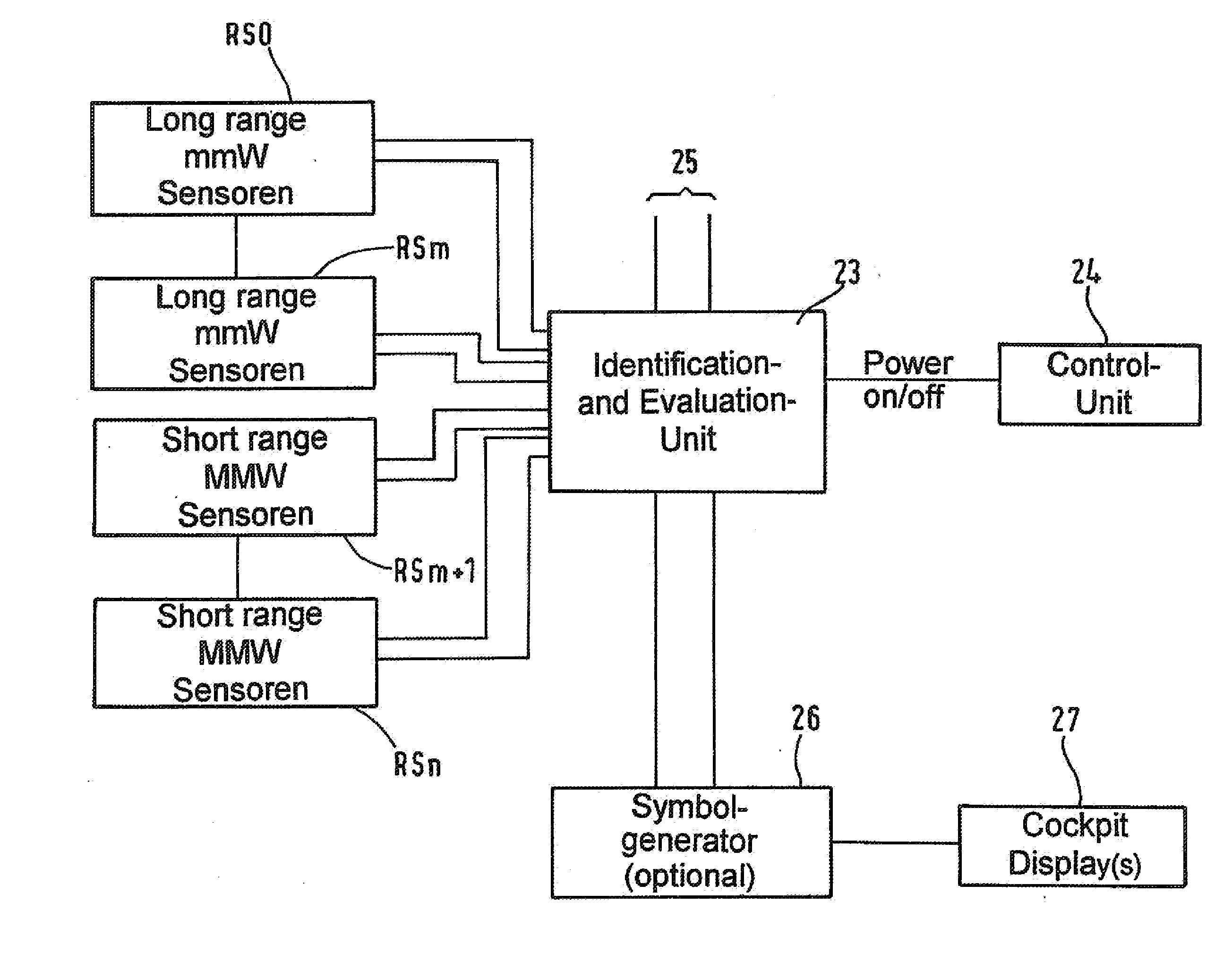
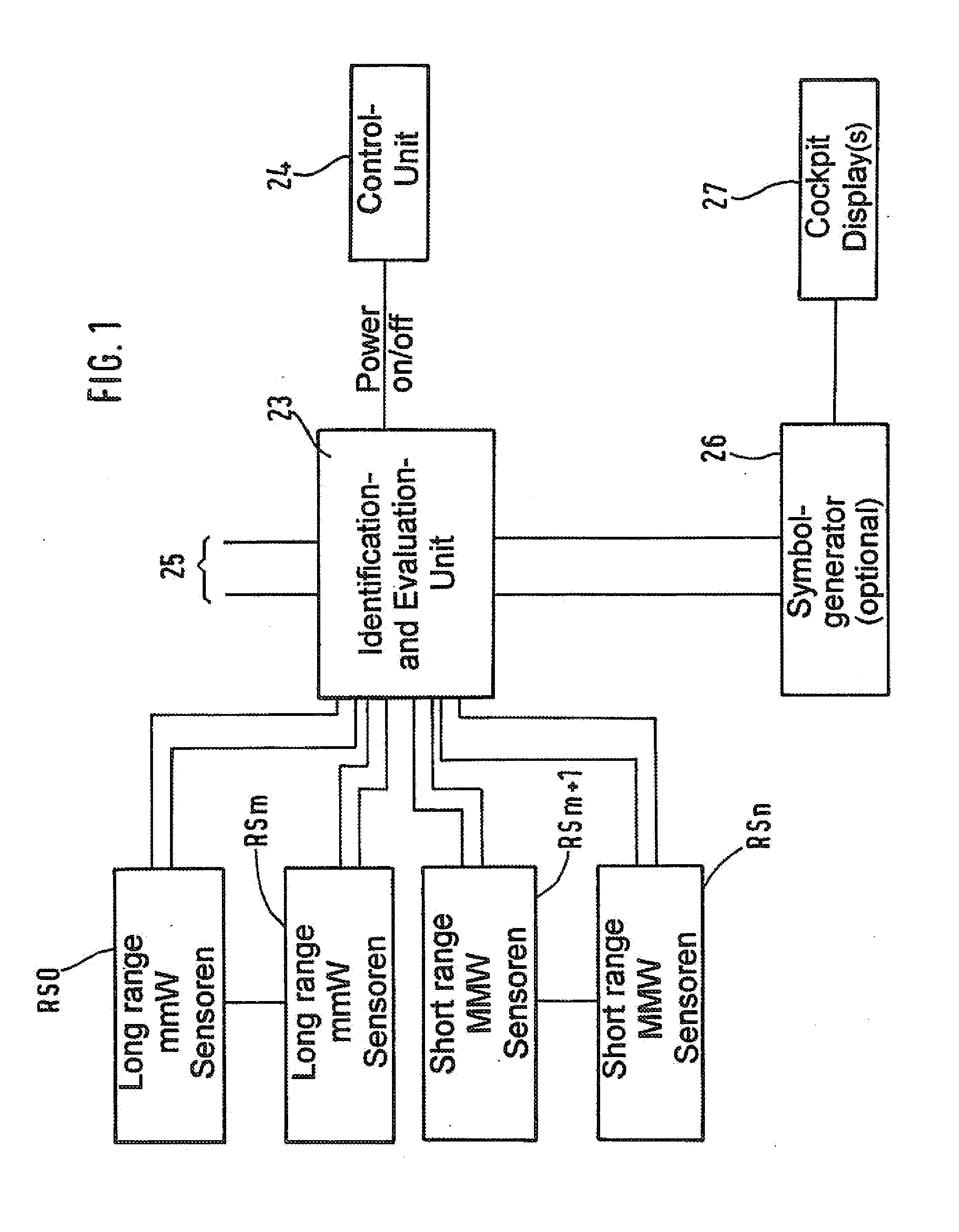
[0006]The assignment, according to the invention, of individual radar sensors operating on varying wavelengths for various distances or ranges (short range and long range) to predetermined scan sectors of the sphere surrounding the helicopter, and the integration thereof into an overall system, results in complete coverage of the relevant helicopter environment, which is not possible with a single scanning radar beam. Hence safety at take-off and landing in difficult terrain and under adverse visibility conditions is enhanced, the operational spectrum is enhanced by warning against collisions during the landing approach of the helicopter in poor visibility, and the awareness of the situation by the pilots in the course of complicated manoeuvres is enhanced. The radar sensors that find application are small components that operate reliably—such as are known, for example, from the distance-warning system in vehicle engineering—and permit a simple and flexible attachment to the structure of the helicopter. These radar sensors operate merely as send-and-receive units and provide their signals to an identification-and-evaluation unit which supplies the display units installed in the cockpit, the so-called cockpit displays. This may be effected either directly or via an interposed symbol generator. It has proved particularly advantageous if the wavelength 24 GHz is used for the short-range waveband and if the wavelength 77 GHz is used for the long-range waveband.
[0009]With the aid of the panoramic warning system according to the invention a good detection of obstacles, especially also of cross-country transmission lines and mountain edges, becomes possible. By virtue of the panoramic coverage, the probability of vertical incidence of the radar beams on cross-country transmission lines that are possibly present is increased, which significantly improves the probability of detection in comparison with prior systems. Such a detection of the lateral distance from mountain edges has, for example, previously not been possible at all.

Problems solved by technology

But obstacle-detection systems based on laser technology are highly dependent on the weather.

Method used


Image

  • Panoramic warning system for helicopters
  • Panoramic warning system for helicopters
  • Panoramic warning system for helicopters

Examples


Embodiment Construction

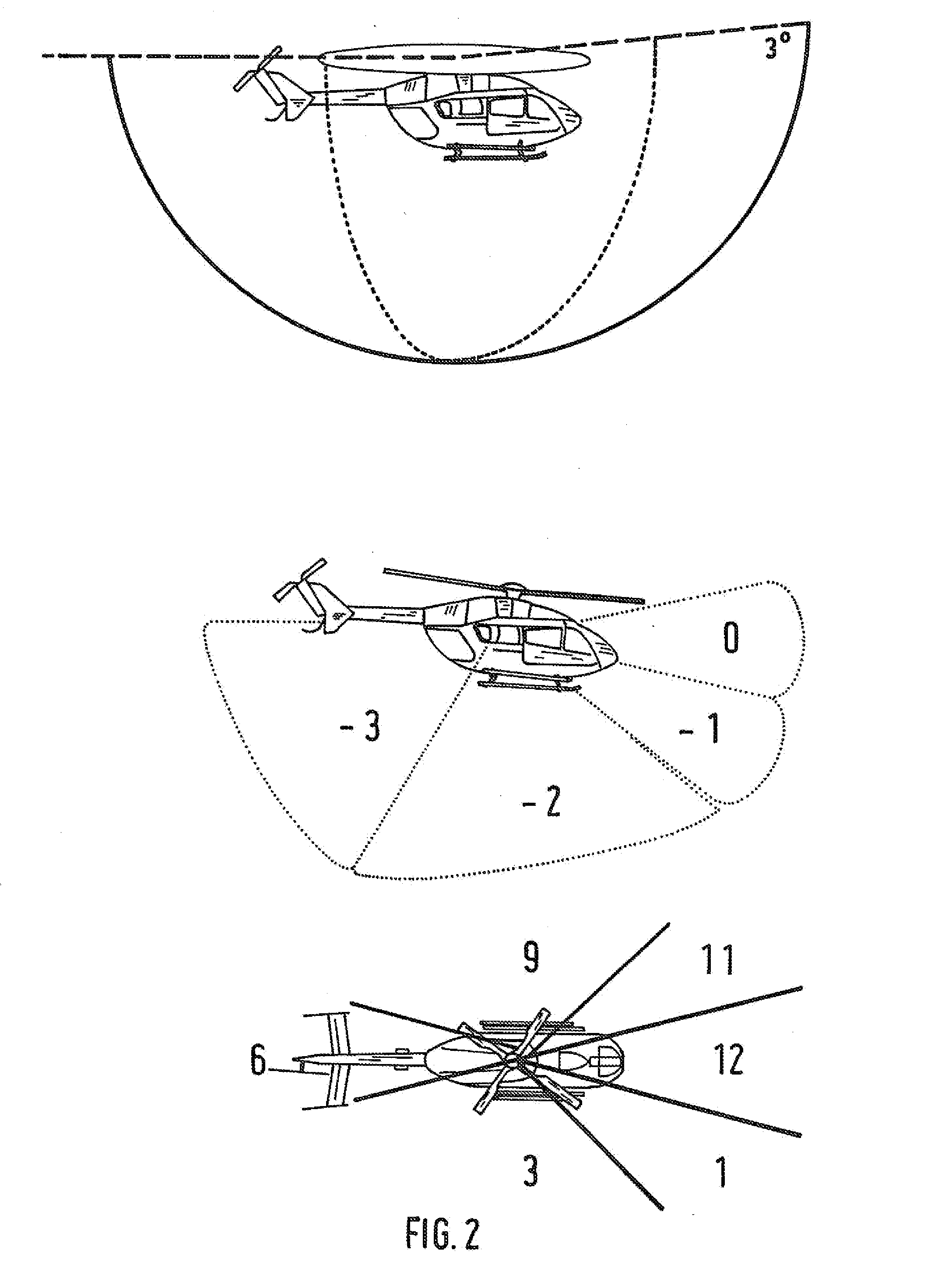
[0018]For the purpose of monitoring the regions represented in FIGS. 2 and 3—designated by means of index numbers 0, −1, −2, −3 and 1, 3, 6, 9, 11, 12, respectively—around a helicopter HS, use is made of a plurality of radar sensors RS distributed in suitable manner on the fuselage structure of the helicopter, of which merely some of the sensors RS0, RSm, RSm+1, RSn have been represented in FIG. 1. The radar sensors RS0 to RSm operate in the long-range region, and the other sensors operate in the short-range region. The signals of the radar sensors representing measured ranges are collected in a central identification-and-evaluation unit 23, evaluated, and assigned to the individual sectors by means of amplitude demodulation or frequency demodulation via the individual identifier / footprint. The identification-and-evaluation unit and consequently the individual radar sensors are capable of being switched on via a control unit 24. In the identification-and-evaluation unit the comparis...


PUM


Abstract

A panoramic warning system for helicopters, for the purpose of detecting obstacles and the proximity of the ground by using a plurality of radar sensors connected to the fuselage structure of the helicopter and which operate on varying wavelengths, the signals of which, representing range information, which are provided with an individual identifier, are compared in a central identification-and-evaluation unit with predetermined warning thresholds and after the assignment to corresponding scan sectors are caused to be displayed on at least one cockpit display.

Description

[0001]Priority is claimed to German Patent Application No. 10 2006 053 354.2, filed on Nov. 10, 2006, the entire disclosure of which is incorporated by reference herein.[0002]The present invention relates to a panoramic warning system for helicopters for the purpose of detecting obstacles and the proximity of the ground by means of radar beams.BACKGROUND[0003]It is known to detect obstacles from a helicopter with a scanning radar beam or laser beam, and also to determine distances from the ground with a radar altimeter. But obstacle-detection systems based on laser technology are highly dependent on the weather.SUMMARY OF THE INVENTION[0004]An object underlying the present invention is to provide a novel, combined, active system for detecting obstacles and terrain, which by using radar beams is able to detect obstacles, in particular also cross-country transmission lines and mountain edges, in a manner suitable for all weathers and better than hitherto, and is able to display such o...

Claims


Application Information

Patent Timeline
IPC IPC(8): G01S13/93G01S13/935
CPCG01S7/03G01S13/87G01S7/22G01S7/062G01S13/935G01S13/933
Inventor REICH, ALEXANDER
Owner AIRBUS HELICOPTERS DEUT GMBH
Learn More