Radar oscillator

a technology of radar and oscillator, which is applied in the direction of oscillation generators, instruments, measurement devices, etc., can solve the problems of disadvantageously difficult to prevent leakage at a high frequency band ranging from 22 to 29 ghz

Inactive Publication Date: 2007-08-09
ANRITSU CORP
View PDF6 Cites 4 Cited by
  • Summary
  • Abstract
  • Description
  • Claims
  • Application Information

AI Technical Summary

Benefits of technology

[0034] In the radar oscillator according to the present invention having first and second LC oscillators, the radar oscillator having a third switch circuit which connects output terminals of the first LC resonator and the second LC resonator to each other in a predetermined period of time after inputting of a pulse signal is stopped is arran

Problems solved by technology

However, as described above, in the conventional radar oscillator 10 in which an output path of an oscillation signal is turned on or off by the switch 15, even though the switch 15 is turned off in an open state, due to imperfection of isolation of the switch 15, leakage from th

Method used


Image

  • Radar oscillator
  • Radar oscillator
  • Radar oscillator

Examples


first embodiment

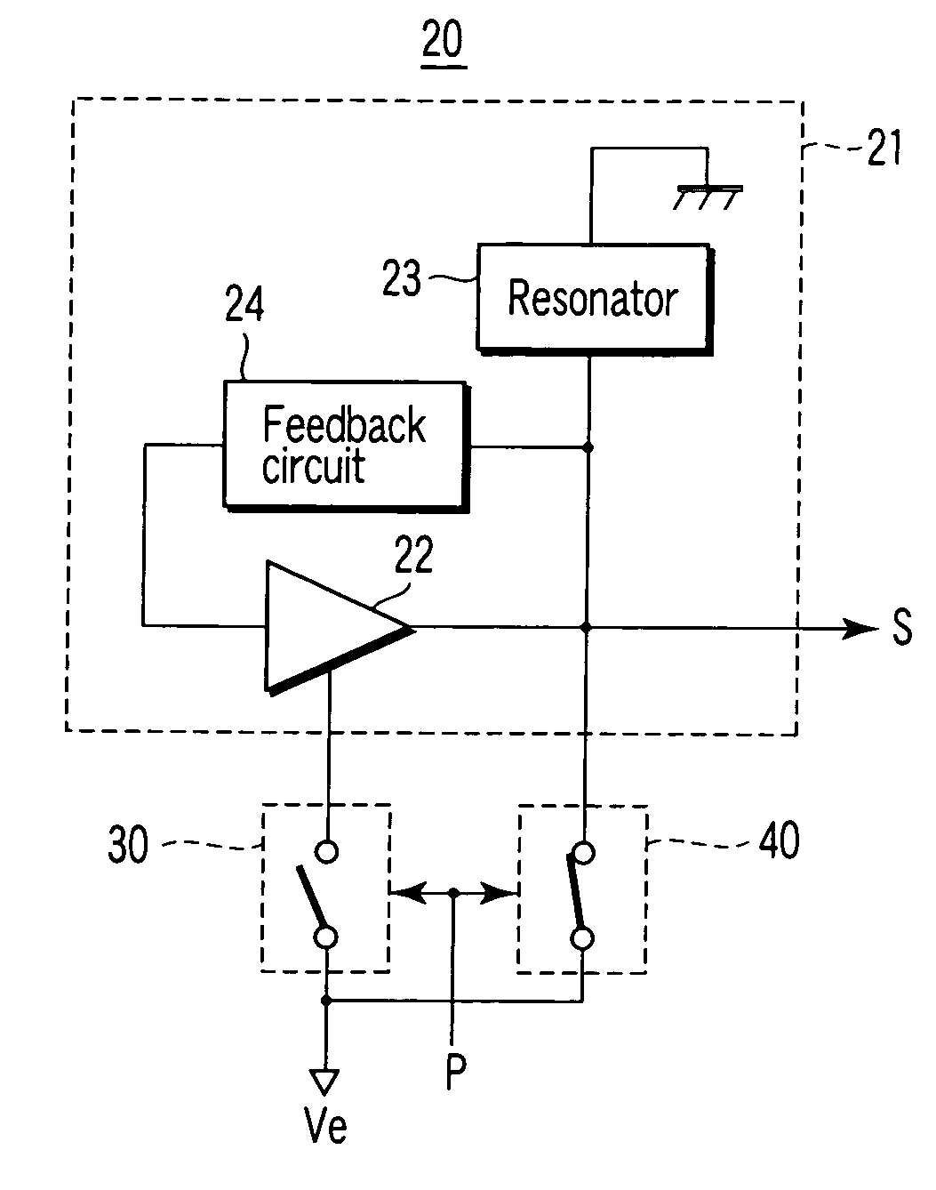
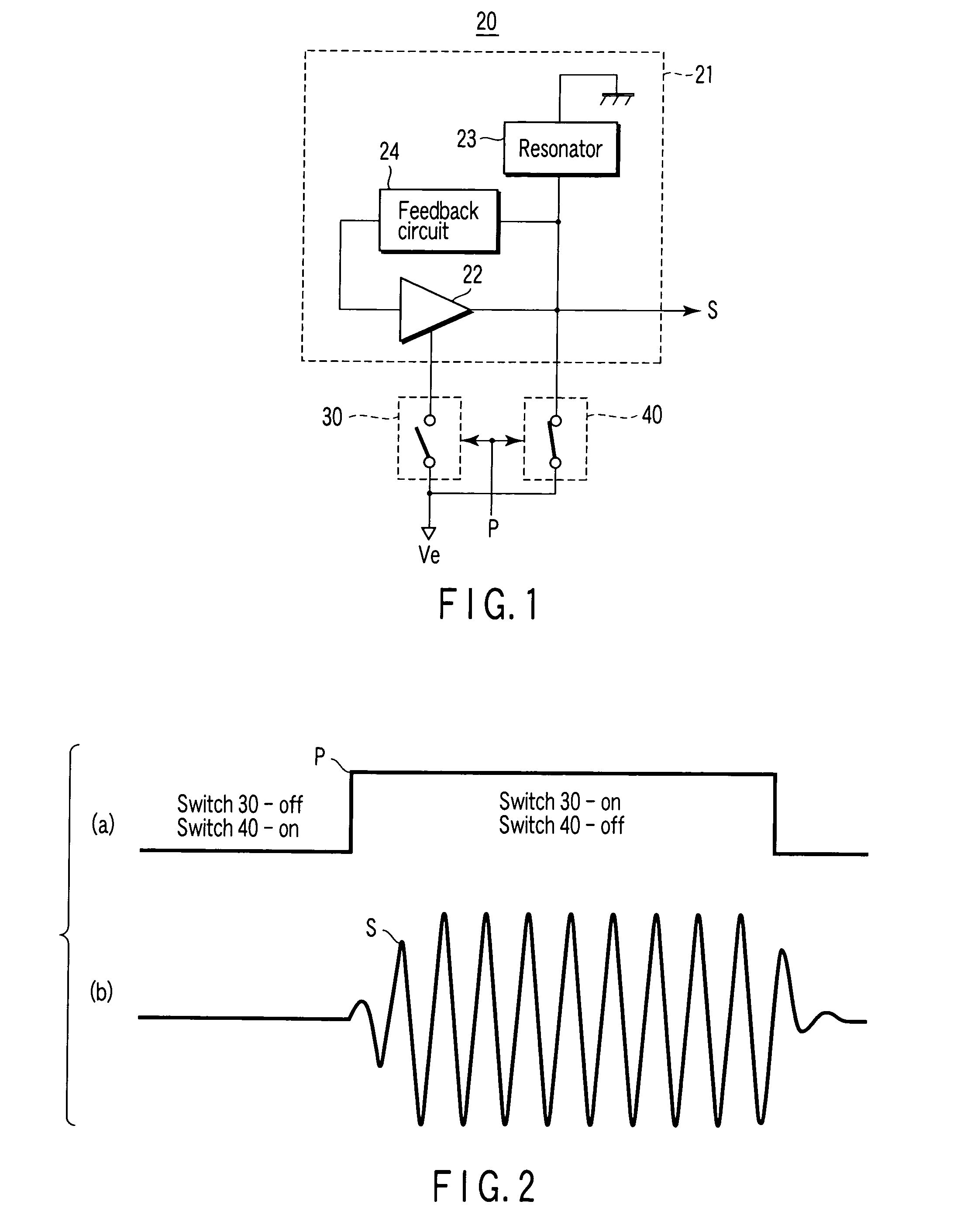
[0049]FIG. 1 is a block diagram shown to explain a configuration of a radar oscillator 20 according to a first embodiment to which the present invention is applied.

[0050] The radar oscillator 20 basically includes: an oscillation unit 21 which has an amplifier 22, an LC resonator 23 which is connected to the amplifier 22, has at least an inductance component and a capacitance component, and resonates at a predetermined resonant frequency, and a feedback circuit 24 which performs positive feedback from an output side of the amplifier 22 to an input side of the amplifier 22, and which outputs an oscillation signal having a frequency determined by the resonant frequency of the LC resonator 23; a first switch circuit 30 which is connected to a power supply unit Ve to the amplifier 22 of the oscillation unit 21, which turns off an electric power supply by the power supply unit Ve to the amplifier 22 in a period in which a pulse signal representing a transmitting period for transmitting ...

second embodiment

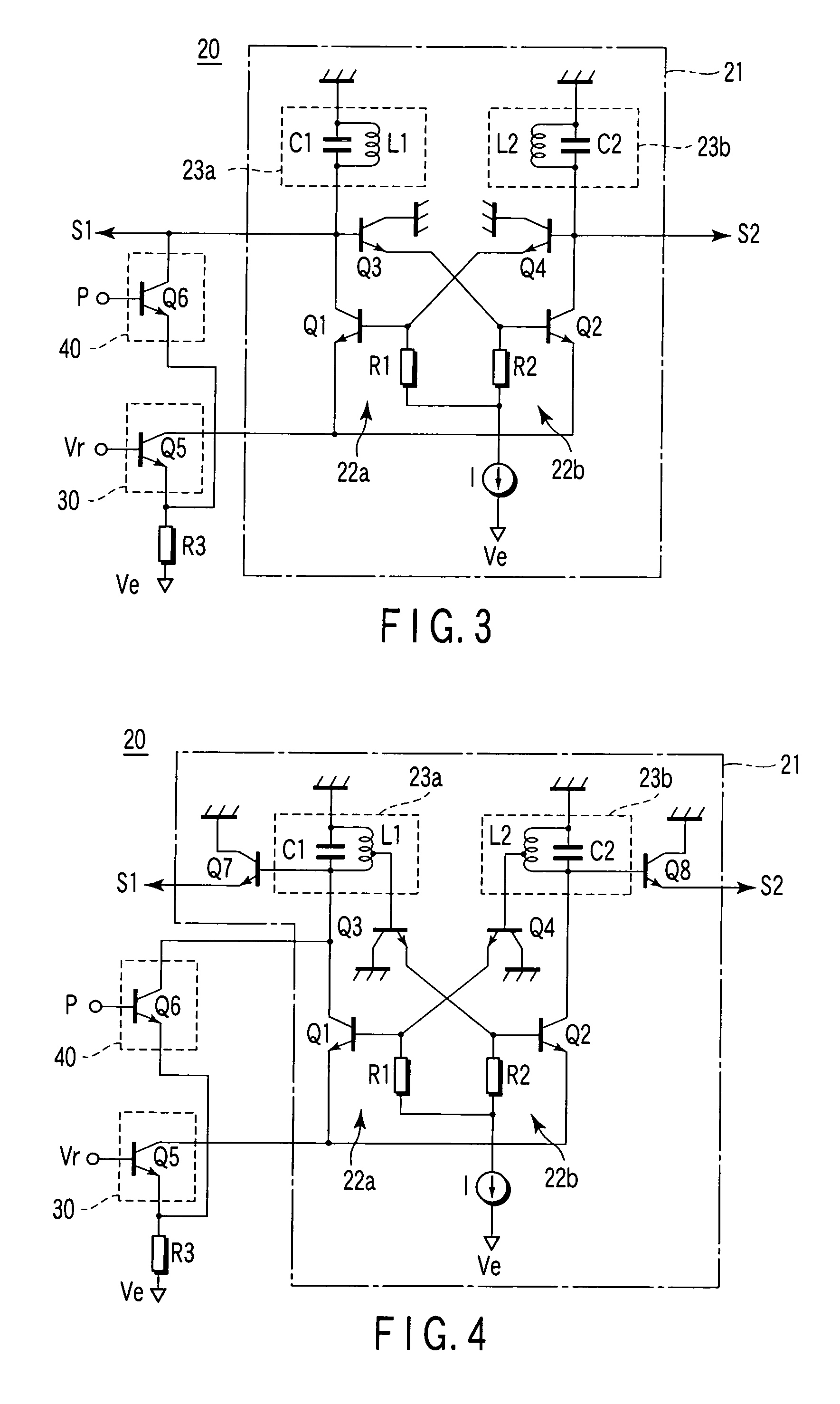
[0068]FIG. 3 is a block diagram shown to explain a configuration of a radar oscillator according to a second embodiment to which the present invention is applied.

[0069] The configuration in FIG. 3 to which the second embodiment is applied shows a more concrete circuit example of a radar oscillator 20 which receives a pulse signal P having a negative logic.

[0070] An oscillation unit 21 of the radar oscillator 20 in FIG. 3 includes a first amplifier 22a constituted by a first LC resonator 23a formed by a parallel connection between a coil L1 and a capacitor C1, a first transistor Q1 using the first LC resonator 23a as a load, and a base resistor R1 of the first transistor Q1.

[0071] The oscillation unit 21 of the radar oscillator 20 has a second amplifier 22b constituted by a second LC fresonator 23b formed by a parallel connection between a coil L2 and a capacitor C2, a transistor Q2 using the second LC resonator 23b as a load, and a base resistor R2 of the transistor Q2.

[0072] In...

third embodiment

[0094]FIG. 4 is a block diagram shown to explain a configuration of a radar oscillator according to a third embodiment to which the present invention is applied.

[0095] In FIG. 4, the same reference numerals as in FIG. 3 denote the same parts as in the radar oscillator according to the second embodiment shown in FIG. 3, and a description thereof will be omitted.

[0096]FIG. 4 shows, as a radar oscillator according to the third embodiment to which the present invention is applied, an example in which bases of transistors Q3 and Q4 constituting buffers are connected to intermediate taps of coils L1 and L2 of first and second LC resonators 23a and 23b, respectively, to further increase Q of the first and second LC resonators 23a and 23b, and transistors Q7 and Q8 (a power supply circuit for these transistors is omitted in the drawing) are arranged as output buffers.

[0097]FIG. 5 is a characteristic diagram showing response characteristics (simulation result) of the radar oscillator acco...


PUM


Abstract

A radar oscillator has an oscillation unit and first and second switch circuits to intermittently output an oscillation signal depending on a pulse signal representing a transmission timing of a transmitting radar signal without causing leakage. The first switch circuit turns off an electric power supply to an amplifier in a non-input period of the pulse signal to set the oscillation unit in a non-oscillation state and turns on the electric power supply to the amplifier in an input period of the pulse signal to set the oscillation unit in an oscillation state. The second switch circuit turns on an electric power supply to an LC resonator in a predetermined period immediately before the pulse signal is input in a period in which the pulse signal is not input to supply a predetermined current to the LC resonator and turns off the electric power supply to the LC resonator at a timing at which the pulse signal is input to stop the supply of the predetermined current to the LC resonator, so that activation of an oscillation operation of the oscillation unit is accelerated.

Description

TECHNICAL FIELD [0001] The present invention relates to a radar oscillator and, more particularly, to a radar oscillator used in an transmitting unit of a small-output radar such as an automotive UWB (ultra-wideband) radar, the radar oscillator employing a technique which eliminates leakage and increases a response speed of the radar oscillator. BACKGROUND ART [0002] An oscillator used in a low-power transmitting unit such as an automotive UWB radar interrupts an output of a quasi-millimeter-wave (22 to 29 GHz) oscillation signal by an external pulse signal representing a transmission timing of a transmitting radar signal. [0003]FIG. 10 shows a configuration of a conventional radar oscillator 10 of this type. [0004] In FIG. 10, an oscillator 11 has an amplifier 12, a resonator 13 connected to an output section of the amplifier 12, and a feedback circuit 14 which feeds back positively an output signal from the amplifier 12 to an input side to oscillate a signal having a frequency det...

Claims


Application Information

Patent Timeline
IPC IPC(8): H03B5/08
CPCG01S7/03G01S7/282G01S13/0209H03B5/1243H03B5/1221H03B5/1215H03B5/1231
Inventor SAITO, SUMIOEJIMA, MASANORIARAYASHIKI, YUTAKA
Owner ANRITSU CORP
Why Eureka
Try Eureka