Image display system

a display system and image technology, applied in non-linear optics, instruments, optics, etc., can solve problems such as deteriorating viewing angles, and achieve the effect of keeping image quality

Active Publication Date: 2008-07-31
INNOLUX CORP
View PDF4 Cites 15 Cited by
  • Summary
  • Abstract
  • Description
  • Claims
  • Application Information

AI Technical Summary

Benefits of technology

[0012]As mentioned above, the image display system of this invention displays the image in a transflective manner, the optical axes of the LC cells are arranged to be parallel to the absorbing axis of the first polarizer when it is aligned, and the LC cells in the light reflecting zones and the light

Problems solved by technology

However, such a small-sized LCD apparatus is more sensitive to the cell gap between the substrates and the

Method used


Image

  • Image display system
  • Image display system
  • Image display system

Examples


Embodiment Construction

[0021]The present invention will be apparent from the following detailed description, which proceeds with reference to the accompanying drawings, wherein the same references relate to the same elements.

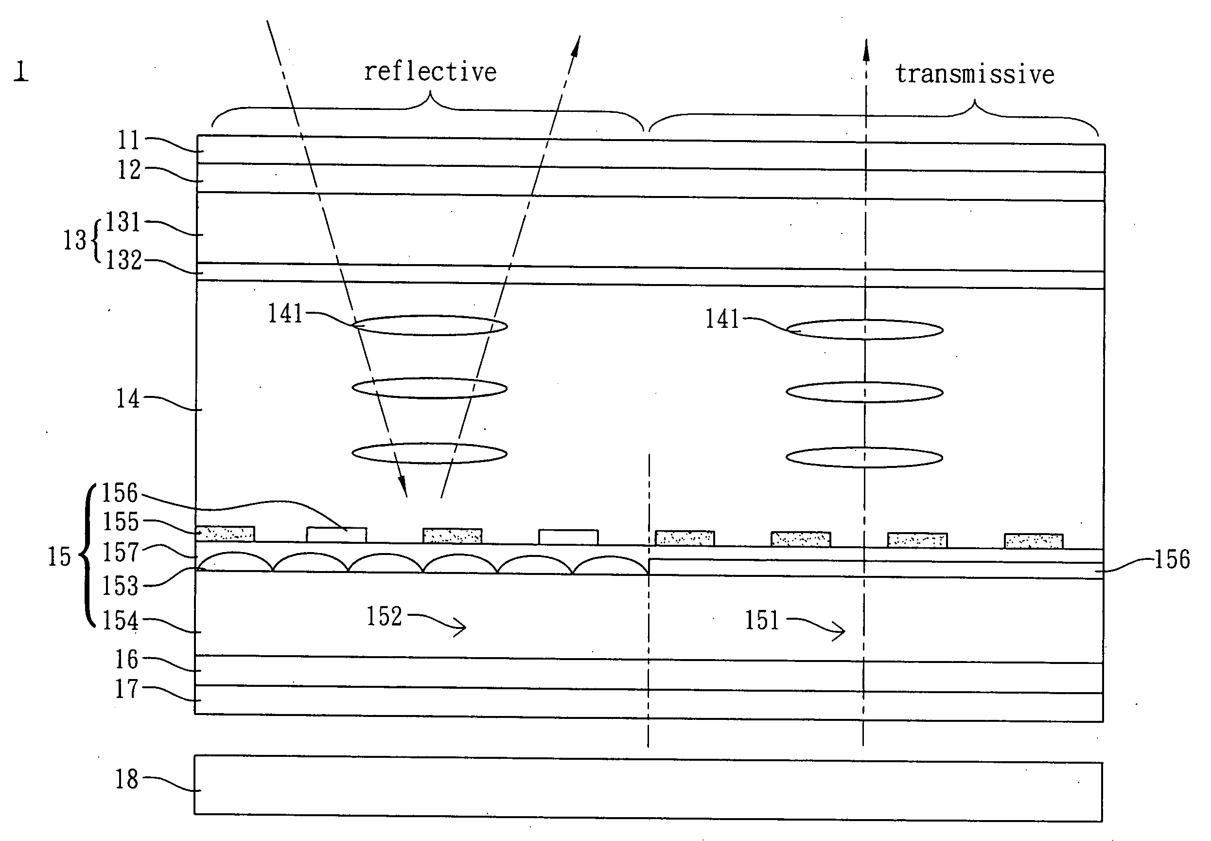
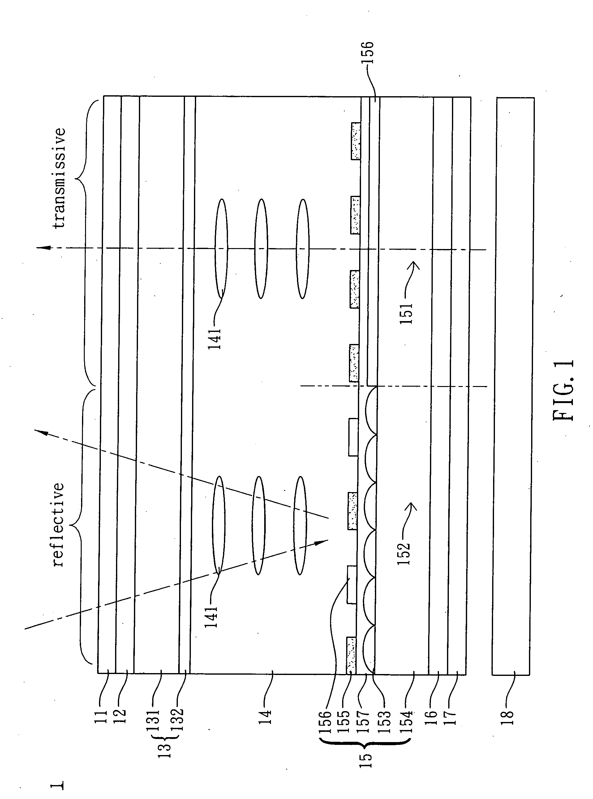
[0022]FIG. 1 is a schematic illustration showing an image display system 1 according to an embodiment of the invention. As shown in FIG. 1, the image display system 1 includes a first polarizer 11, a first retardation plate 12, a first substrate 13, a LC layer 14, a second substrate 15, a second retardation plate 16, a second polarizer 17 and a backlight module 18. In the embodiment, the first polarizer 11 to the second polarizer 17 are assembled together to form a LCD panel, and the backlight module 18 may be assembled with the LCD panel to form a LCD apparatus.

[0023]The first polarizer 11 and the first retardation plate 12 are disposed at the same side of the first substrate 13 and in correspondence with the LC layer 14. The first retardation plate 12 is disposed between the first p...


PUM


Abstract

An image display system includes a first polarizer, a first substrate, a liquid crystal (LC) layer and a second substrate. The first polarizer is disposed on the first substrate. The LC layer has a plurality of LC cells each having an optical axis parallel to an absorbing axis of the first polarizer. The second substrate has a plurality of light transmitting zones and a plurality of light reflecting zones. A plurality of reflectors is disposed within the light reflecting zone. The LC cells are horizontally disposed between the first substrate and the second substrate. The LC cells corresponding to the light reflecting zones are driven in a normally white mode, while the LC cells corresponding to the light transmitting zones are driven in a normally black mode.

Description

CROSS REFERENCE TO RELATED APPLICATIONS[0001]This Non-provisional application claims priority under 35 U.S.C. §119(a) on Patent Application No(s). 096101950 filed in Taiwan, Republic of China on Jan. 18, 2007, the entire contents of which are hereby incorporated by reference.BACKGROUND OF THE INVENTION[0002]1. Field of Invention[0003]The invention relates to an image display system and, in particular, to an image display system with transversely aligned liquid crystals.[0004]2. Related Art[0005]The liquid crystal display (LCD) apparatus is a flat display system. The LCD apparatuses may be classified into a twisted nematic (TN) type, a multi-domain vertical alignment (MVA) type, an in-plane switching (IPS) type and a fringe-field switching (FFS) type according to the arrangements of the liquid crystals. The MVA type, the IPS type and the FFS type are frequently seen in the field of the wide viewing angle display technology.[0006]The typical IPS or FFS type LCD apparatus includes top ...

Claims


Application Information

Patent Timeline
IPC IPC(8): G02F1/1335
CPCG02F1/133555G02F2203/66G02F2203/64G02F1/134363
Inventor CHANG, WEI-CHIHHSU, SU-JUNG
Owner INNOLUX CORP
Why Eureka
Try Eureka