Electronic Device and Case for the Same

a technology for electronic devices and cases, applied in the direction of casings/cabinets/drawers, instruments, casings/cabinets/drawers, etc., can solve the problems of hard to reduce the size and weight of electronic devices, and achieve the effect of increasing the effective space for disposing elements, reducing deformation, and enhancing strength

Active Publication Date: 2008-07-31
MITSUBISHI ELECTRIC CORP
View PDF3 Cites 37 Cited by
  • Summary
  • Abstract
  • Description
  • Claims
  • Application Information

AI Technical Summary

Benefits of technology

[0006]Exemplary embodiment of the present invention provides an electronic device capable of increasing an effective space for disposing elements thereof, enhancing strength to reduce deformation thereof and reducing creak.

Problems solved by technology

Therefore, there is limitation for disposing the substrate and the battery in the space defined by the case, so that it is very hard to reduce a size and weight of an electronic device.

Method used


Image

  • Electronic Device and Case for the Same
  • Electronic Device and Case for the Same
  • Electronic Device and Case for the Same

Examples


embodiment 1

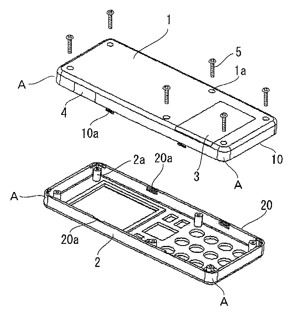
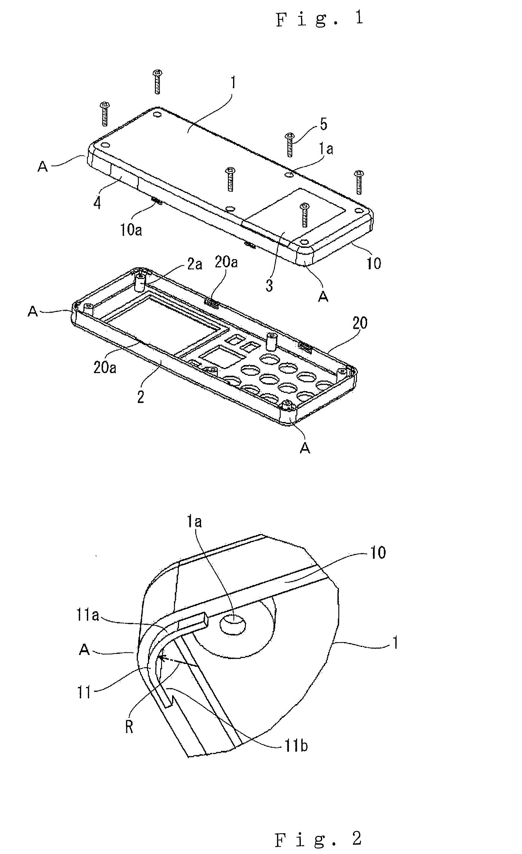
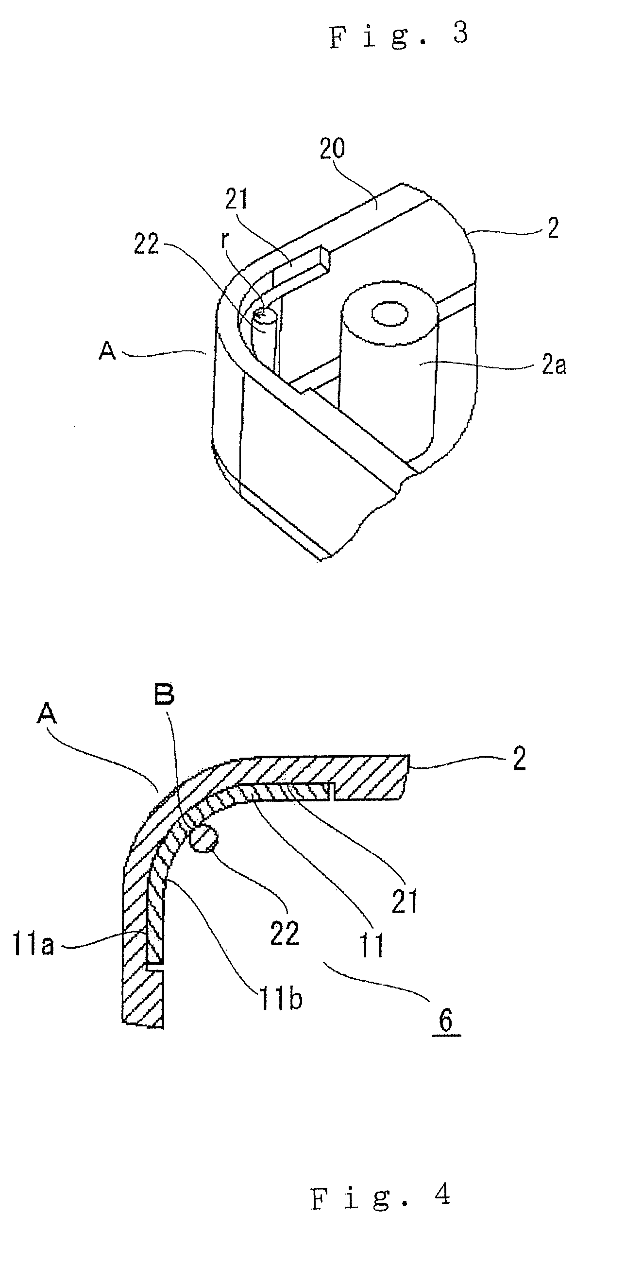
[0038]FIGS. 1 through 4 relate to an electronic device according to Embodiment 1. In detail, FIG. 1 is an exploded perspective view illustrating a case for an electronic device according to a first exemplary embodiment of the present invention, FIG. 2 is a perspective view illustrating a corner portion of a first engaging portion of a first member in the case in FIG. 1, FIG. 3 is a perspective view illustrating a corner portion of a second engaging portion of a second member in the case in FIG. 1, and FIG. 4 is a cross-sectional view illustrating positions of elements in the corner portion when the first engaging portion and the second engaging portion in FIG. 1 are combined with each other. The electronic device in Embodiment 1 is a cellular phone. Same reference numerals will be used for same or likely elements throughout each Embodiment, and repetitive explanation will be omitted.

[0039]A case of the cellular phone includes a first member 1 and a second member 2. The first member ...

embodiment 2

[0048]FIGS. 5 through 11 are figures for explaining an electronic device according to the second exemplary embodiment. FIGS. 5 and 6 show a first modified example of the corner portion engaging member in FIGS. 3 and 4. FIGS. 7 and 8 show a second modified example of the corner portion engaging member in FIGS. 2 and 4. FIGS. 9A shows a third modified example of the corner portion engaging member in FIG. 3. FIGS. 10 and 11 show a fourth modified example of the corner portion engaging member in FIGS. 2 and 4. In detail, FIGS. 5 and 9A are a perspective view illustrating a corner portion of a second engaging portion of a second member corresponding to the above FIG. 3. FIG. 9B is an enlarged plan view illustrating an inner supporting member in FIG. 9A. FIGS. 6, 8 and 11 are a cross-sectional view illustrating positions of elements in the corner portion when a first engaging portion and the second engaging portion are combined with each other. FIGS. 7 and 10 are a perspective view illust...

embodiment 3

[0055]FIGS. 12 through 15 are figures for explaining a case of an electronic device according to the third exemplary embodiment. FIG. 12 is an exploded perspective view illustrating a case for an electronic device according to a third exemplary embodiment of the present invention. FIG. 13 is a perspective view illustrating a corner portion of a first engaging portion of a first member in the case in FIG. 12. FIG. 14 is a perspective view illustrating a corner portion of a second engaging portion of a second member in the case in FIG. 12. FIG. 15 is a cross-sectional view illustrating positions of elements in the corner portion when the first engaging portion and the second engaging portion in FIG. 12 are combined with each other. FIGS. 16 and 17 show a first modified example of the corner portion in FIGS. 14 and 15. FIGS. 18 and 19 show a second modified example of the corner portion in FIGS. 13 and 15. In detail, FIG. 16 is a partial perspective view corresponding to FIG. 14. FIG. ...


PUM


Abstract

An electronic device has a case that is formed by combining first and second members respectively having first and second engaging portions formed along an outer circumferential portion thereof such that the first and second members make contact with each other. The electronic device includes a corner engaging member having a rib, an outer supporting member and an inner supporting member. The rib is formed at a corner portion of the first engaging portion such that the rib is curved along the corner portion. The outer supporting member is formed at a corner portion of the second engaging portion, which corresponds to the corner portion of the first engaging portion. The outer supporting member makes contact with an outer circumferential surface of the rib. The inner supporting member makes line-contact with an inner circumferential surface of the rib. The rib is inserted between the outer supporting member and the inner supporting member.

Description

BACKGROUND OF THE INVENTION[0001]1. Field of the Invention[0002]The present invention relates to an electronic device and a case for the electronic device. More particularly, the present invention relates to a mobile electronic device, for example, such as a mobile phone, a personal digital assistance and a case for the electronic device.[0003]2. Description of the Related Art[0004]According to the prior art disclosed in the claim 1 and FIG. 1 of Japan Patent Publication No. 2001-119455, the case for enhancing strength thereof and reducing deformation and creak thereof includes a front case and a rear case, and a substrate is disposed in a cavity defined by the front case and the rear case. The rear case has a concave portion, and a sidewall having the concave portion has a relatively thicker thickness. A rib is formed parallel with the sidewall to define a battery section and an antenna section.[0005]However, according to the prior art described above, an effective space is reduced...

Claims


Application Information

Patent Timeline
Patent Type & Authority Applications(United States)
IPC IPC(8): H04M1/00H05K5/02
CPCH04M1/0249H04B1/38
Inventor IMAIZUMI, MASARUKAWAHARA, YOHEISAITO, KOJINAKATA, EIJI
Owner MITSUBISHI ELECTRIC CORP
Why Eureka
Try Eureka