Light source driving apparatus, display device having the same, and driving method thereof

a technology of light source and display device, which is applied in the direction of process and machine control, television systems, instruments, etc., can solve the problems of difficult to accurately input the pulse waveform of a driving current, the complexity of the panel manufacturing process of the lcd device, and the difficulty of reducing the manufacturing cost of implementing a heat radiation mechanism, so as to reduce the manufacturing cost and increase the efficiency. , the effect of increasing the optical power

Inactive Publication Date: 2008-08-07
SAMSUNG ELECTRONICS CO LTD
View PDF3 Cites 32 Cited by
  • Summary
  • Abstract
  • Description
  • Claims
  • Application Information

AI Technical Summary

Benefits of technology

[0048]Therefore, the optical power can be increased by supplying the plurality of the light sources with the same electric current of the same driving frequency and the same duty ratio. The supply of a low-level driving current can raise the efficiency. Since it is possible to utilize the light source driving apparatus to supply a low-level driving current, the manufacturing costs required to implement a heat radiation mechanism can be reduced. Furthermore, the overall driving speed of the system can be enhanced by increasing the driving speed of the plurality of the light sources by virtue of the low-level driving current.

Problems solved by technology

However, an LCD device's panel manufacture process is complicated and its luminance is quite low.
In this case, while the optical power can be increased by driving all the laser diodes of the light source module 20 together, it becomes difficult to accurately input the pulse waveform of a driving current I with a specific duty ratio to the light source module 20 due to the high level of the driving current I required.
As a result, even when a plurality of the laser diodes LDn are implemented in the light source module 20, the designer cannot acquire his / her intended optical power.
As a result, the system efficiency may be degraded.
Since the light source driver 30 has to produce the high-level driving current, a heat radiation mechanism such as a heat sink is also required, which causes an increase in manufacturing costs.

Method used


Image

  • Light source driving apparatus, display device having the same, and driving method thereof
  • Light source driving apparatus, display device having the same, and driving method thereof
  • Light source driving apparatus, display device having the same, and driving method thereof

Examples


Embodiment Construction

[0060]Certain exemplary embodiments of the present invention will now be described in greater detail with reference to the accompanying drawings.

[0061]In the following description, same drawing reference numerals are used for the same elements even in different drawings. The matters defined in the description, such as detailed construction and elements, are provided to assist in a comprehensive understanding of the invention. Thus, it is apparent that the present invention can be carried out without those specifically defined matters. Also, well-known functions or constructions are not described in detail since they would obscure the invention with unnecessary detail.

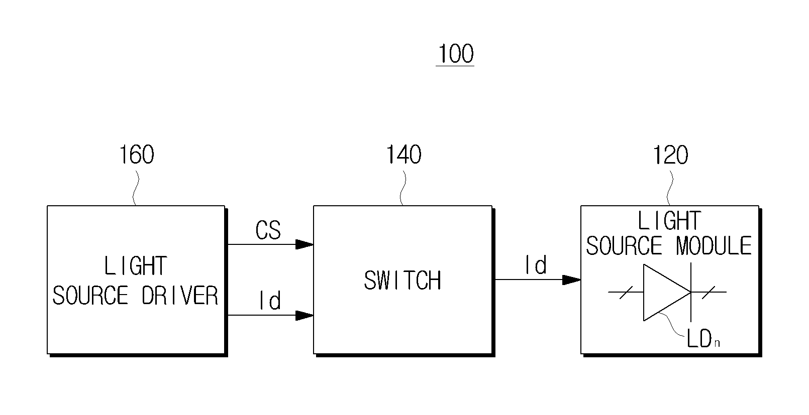
[0062]FIG. 3 is a simplified diagram of a light source driving apparatus according to an exemplary embodiment of the present invention.

[0063]The light source driving apparatus 100 of FIG. 3 comprises a switch 140 coupled to a light source module 120, and a light source driver 160 for providing a control signal CS and a ...


PUM


Abstract

A light source driving apparatus for time-dividing and driving a plurality of light sources, a display device having the same, and a driving method thereof are provided. The light source driving apparatus includes a light source module including a plurality of light sources; a light source driver which outputs a driving current to drive the light sources; and a switch which selectively feeds the driving current to the light sources respectively and sequentially drives the plurality of the light sources. The light source driver outputs a low-level driving current to drive the light sources, and thus the driving speed, the system efficiency and the optical power can be increased and the manufacturing cost can be reduced.

Description

CROSS-REFERENCE TO RELATED APPLICATIONS[0001]This application claims priority from Korean Patent Application No. 10-2007-0012116, filed on Feb. 6, 2007, in the Korean Intellectual Property Office, the disclosure of which is incorporated herein by reference in its entirety.BACKGROUND OF THE INVENTION[0002]1. Field of the Invention[0003]Apparatuses and methods consistent with the present invention relate to a light source driver, a display having the same, and driving the display, and more particularly, to a light source driving apparatus that enhances a driving speed and a driving efficiency and reducing a manufacture cost by dividing a plurality of light sources into blocks, and driving the divided plurality of light sources, and a display apparatus having the light source driving apparatus, and a driving method thereof.[0004]2. Description of the Related Art[0005]Recently, one of the major concerns in regards to a display device is implementing a display part of the display device ...

Claims


Application Information

Patent Timeline
Patent Type & Authority Applications(United States)
IPC IPC(8): H05B41/36H05B44/00
CPCH05B33/0818H05B33/0851H05B33/0848H05B45/14H05B45/10H05B45/37H04N5/74H04N5/63
Inventor JEONG, JIN-GILLEE, SEUNG-YOLEE, JUNG-SEOB
Owner SAMSUNG ELECTRONICS CO LTD
Why Eureka
Try Eureka