Leg type mobile robot

a mobile robot and leg-type technology, applied in the field of leg-type mobile robots, can solve the problems of reducing the longevity of the elastic member, reducing the locomotion speed of the leg-type member, and exhibiting a relatively small stroke of compression, so as to increase the locomotion speed, increase the resistance force, and move easily

Active Publication Date: 2008-08-07
HONDA MOTOR CO LTD
View PDF7 Cites 18 Cited by
  • Summary
  • Abstract
  • Description
  • Claims
  • Application Information

AI Technical Summary

Benefits of technology

[0016]With this feature, the leg type mobile robot is configured to convert the motion of the movable portion with respect to the foot flat portion in the (first) direction perpendicular to the plane containing the ground contact end of the foot, to the motion of the shock absorber (expanding or contracting) in the (second) direction which forms an acute angle with the plane containing the ground contact end of the foot, by swinging motion of the motion direction conversion mechanism. Furthermore, the shock absorber may be disposed so that it is allowed to expand or contract in the direction which forms an acute angle with the plane containing the ground contact end of the foot, and thus the characteristics of the reaction force received by the action of the foot stepping on the ground surface may become nonlinear. The orientation of the shock absorber as described above (i.e., such that the expanding / contracting direction thereof is configured to form an acute angle with the plane containing the ground contact end of the foot) makes it possible to have a great stroke (displacement) of the expanding / contracting motion of the shock absorber even if the horizontal dimensions of the foot (the length in its front-back direction or the width in its right-left direction) is not wide enough. Therefore, the same advantageous effects may be expected as in the case, described above, where the second direction is a direction parallel to the plane containing the ground contact end of the foot.
[0017]The aforementioned leg type mobile robot as consistent with the present invention may comprise an additional leg or legs having or not having the above features, as long as at least one leg is configured in accordance with the embodiments of the present invention as described above. The number of legs may be chosen depending upon its particular application. Also, the foot, or each of the foots joined to the distal ends of the corresponding legs through the corresponding second joints, may comprise more than one pair of the shock absorber and the motion direction conversion mechanism, in addition to the foot flat portion and the movable portion (each provided singly). The more than one pair of the shock absorber and the motion direction conversion mechanism may be arranged symmetrically with respect to a plane containing a center of the second joint and perpendicular to a plane containing the ground contact end of the foot.
[0018]To be more specific, in an exemplary embodiment, the foot that comprises a foot flat portion, a movable portion, a shock absorber and a motion direction conversion mechanism as described above may further comprise a second shock absorber, and a second motion direction conversion mechanism. The second shock absorber may comprise third and fourth end portions allowed to move closer to or away from each other in a third direction different from the first direction, wherein the third end portion of the second shock absorber is joined to a third point of the movable portion. The second motion direction conversion mechanism is joined swingably to the fourth end portion of the second shock absorber and to a fourth point of the movable portion, respectively, and configured to convert a motion of the movable portion in the first direction to a motion of the fourth end portion of the second shock absorber in the third direction with respect to the third point of the movable portion. The third and fourth points of the movable portion may be disposed symmetrical to the first and second points of the movable portion, respectively, with respect to a plane containing a center of the second joint and perpendicular to a plane containing the ground contact end of the foot.
[0019]With this feature, in the leg type mobile robot, a plurality of units in each of which the motion direction conversion mechanism and the shock absorber are provided in pair are arranged in such a manner that they are symmetrical to each other with respect to a plane containing a center of the second joint and perpendicular to a plane containing the ground contact end of the foot; therefore, shocks (impacts) received for example from front-back and / or right-left directions may be absorbed in a well-balanced manner at positions symmetrical with respect to the plane containing the center of the second joint and perpendicular to the plane containing the ground contact end of the foot. It is to be appreciated that the expanding / contracting direction (second or third direction) of the shock absorber may be arranged in any orientation in plan view, such as front-back or right-left or any other directions in-between. Such a symmetrical arrangement of more than one pair of the shock absorber and the motion direction conversion mechanism may allow the leg type mobile robot to flexibly respond to any required change in posture (to increase its locomotion speed) or in locomotion direction, and to easily move even on a bad road. Furthermore, provision of a plurality of units (pairs) of the shock absorber and the motion direction conversion mechanism in the leg type mobile robot as described above may serve to distribute the load of its self weight upon the foot.
[0020]The aforementioned leg type mobile robot may have a plurality of combinations each formed of the shock absorber and the motion direction conversion mechanism. Each of the shock absorbers in the combinations is configured such that repulsive force to repel an external force in an expanding / contracting direction thereof is adjustable based on floor reaction force acting on the shock absorber according to a position on the foot.
[0021]With this feature, in the leg type mobile robot, each of the shock absorbers in the combinations is configured such that repulsive force is adjustable based on the floor reaction force. Thus, strength of the repulsive force of the respective shock absorbers may be set according to a distance from an area in which a stronger floor reaction force is applied to the foot, to each of the shock absorbers. In other words, a shock absorber provided nearer to the aforementioned area may be set to have a stronger repulsive force. On the other hand, a shock absorber provided farther to the area may be set to have a weaker repulsive force. Further, the area in which a stronger floor reaction force is applied to the foot varies during a forward travel and a backward travel of the robot, or when the robot walks or runs. Strength of the repulsive force of each of the shock absorbers is adjustable according to how the robot travels. This makes it possible for the leg type mobile robot to walk and run with stability according to the floor reaction force to the foot during both landing on and leaving off from the floor.

Problems solved by technology

The elastic member typically made of rubber exhibits a relatively small stroke (displacement) of compression, which could possibly be insufficient for fully absorbing the shock caused by landing, particularly for removing a high-frequency component thereof during a landing period for which a foot is landed on the ground.
Furthermore, the relatively small stroke (displacement) of compression of the elastic member provided in this leg type mobile robot would reduce the longevity of the elastic member, each time when the elastic member is compressed to produce a sufficient reaction force during a bracing period for which one foot is braced against the ground to lift the other foot.

Method used


Image

  • Leg type mobile robot
  • Leg type mobile robot
  • Leg type mobile robot

Examples


first embodiment

[Bipedal Mobile Robot]

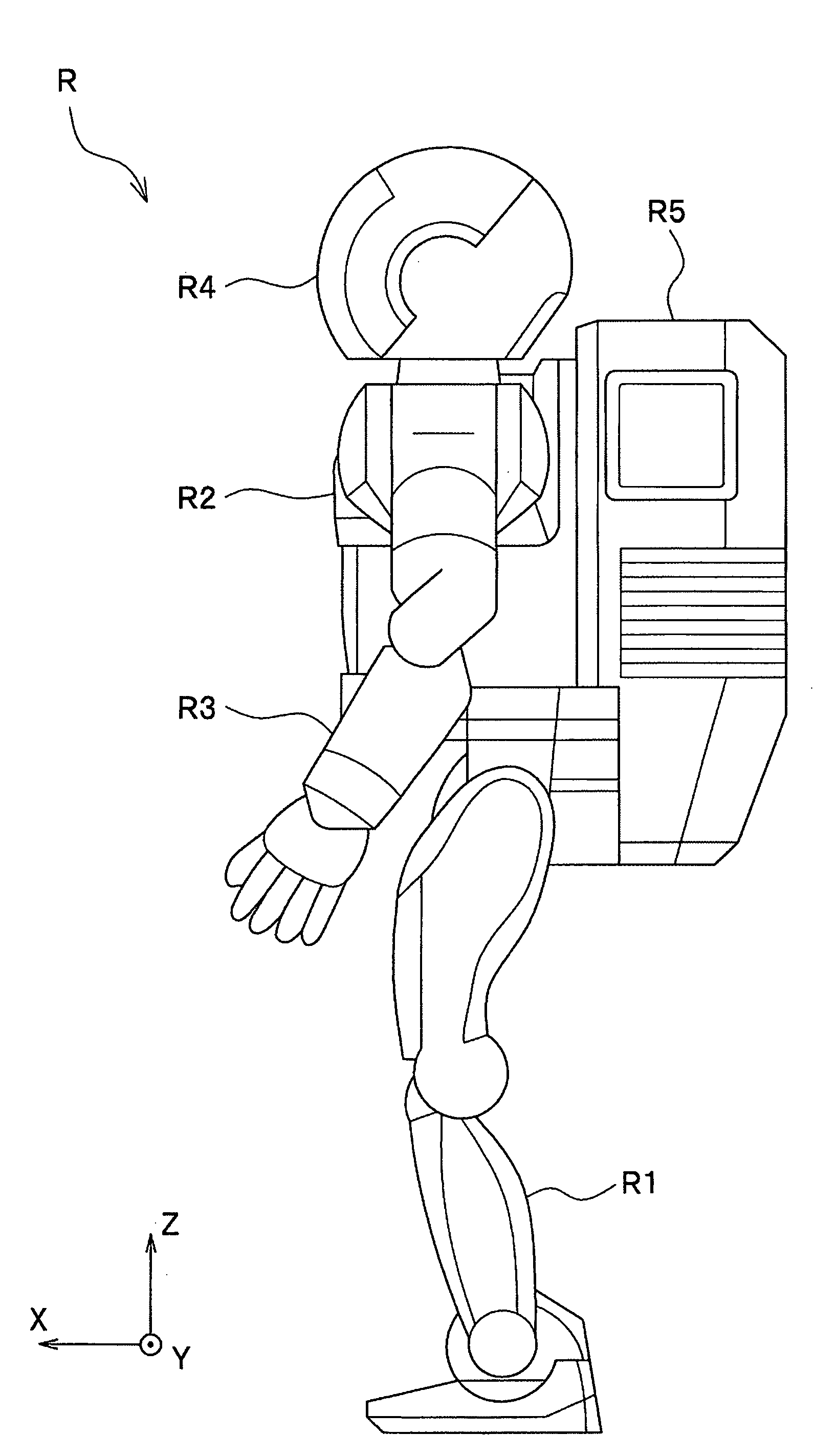
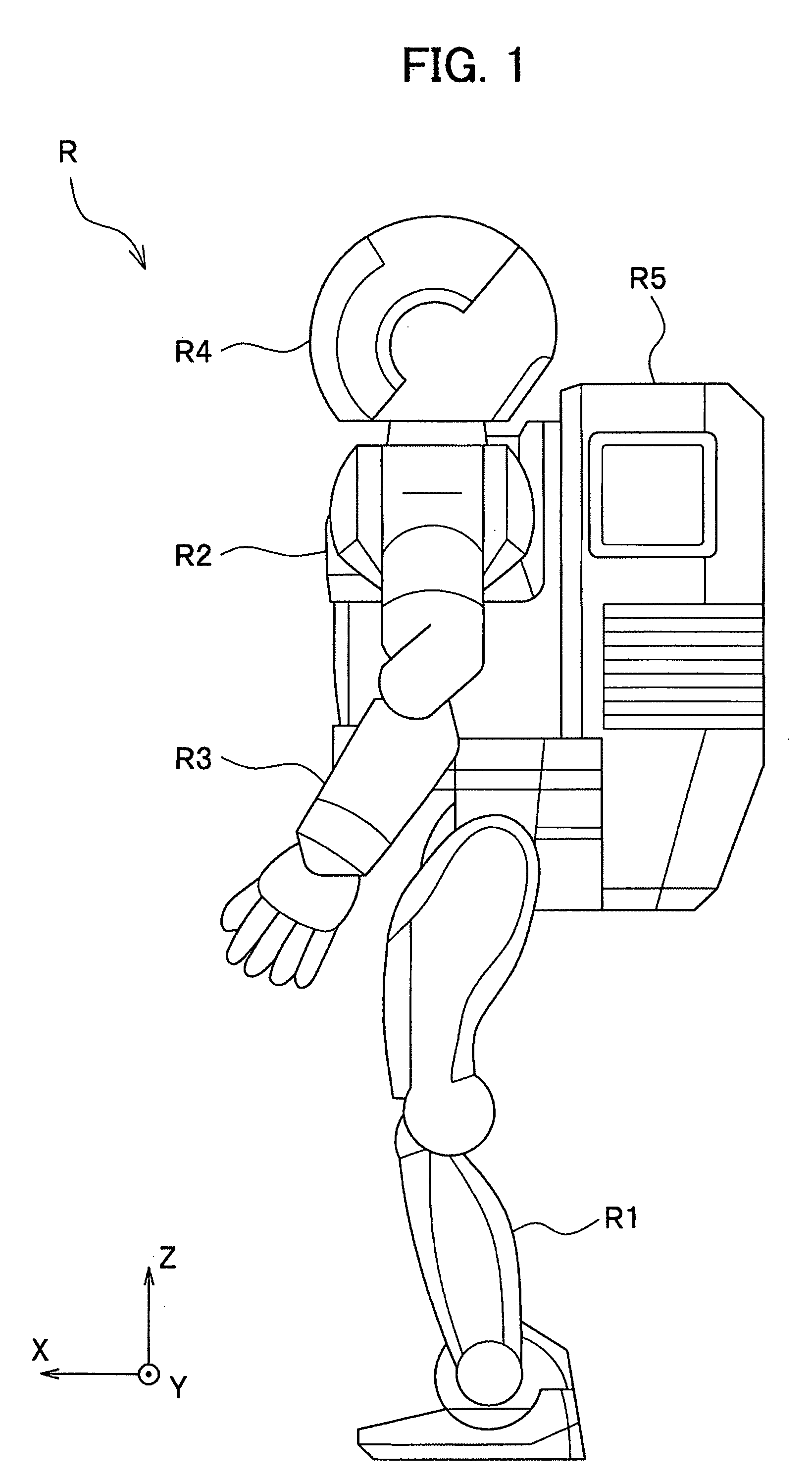
[0048]Referring now to FIG. 1, a bipedal mobile robot according to a first embodiment of the present invention will be described. The front-back direction, right-left direction and vertical direction of the bipedal mobile robot are represented by X-axis (the front side of robot R is designated as front or normal direction), Y-axis (the left side of the robot R is designated as normal direction) and Z-axis (the upper side of robot R is designated as normal direction), respectively. Expressions for the position and direction or the like of the bipedal mobile robot are described on the basis of a state where the bipedal mobile robot takes an upright standing posture.

[0049]As shown in FIG. 1, a bipedal mobile robot (hereinafter referred to simply as ‘robot’) R stands and autonomously moves (walks, runs, or otherwise) using two legs R1 (only one leg is shown) in the same manner as a human. The bipedal mobile robot R in the present embodiment includes a body R2, two ...

second embodiment

[0092]A bipedal mobile robot according to a second embodiment is similar to the first embodiment which has been described with reference to FIGS. 1 through 4, except that a four-bar linkage is used in the shock absorbing assembly 34 of the foot 17. Therefore, the same elements will be designated by the same reference characters, and a duplicate description thereof will be omitted. An alternative shock absorbing assembly in the foot will hereafter be described with reference made to FIG. 13 (to FIGS. 3 and 4 where appropriate).

[0093]FIG. 13 schematically shows a foot of a bipedal mobile robot according to the second embodiment. The bipedal mobile robot according to the second embodiment, as in the first embodiment, includes four shock absorbing assemblies (though not all are shown) over the foot flat portion 131 of the foot 17. FIG. 13 shows a left-side half of the foot 17 (17R) of the robot R standing upright, as viewed from the normal direction of X-axis (i.e., right foot is viewed...

third embodiment

[0101]A bipedal mobile robot according to a third embodiment is similar to the first embodiment except that, in the foot 17 shown in FIG. 3, shock absorbing ability of the two shock absorbing assemblies 34c, 34d is different from shock absorbing ability of the two shock absorbing assemblies 34a, 34b, which are disposed in parallel across the force sensor 32 in a front-back direction thereof (in the X-axis direction). Therefore, the same elements will be designated by the same reference characters, and a duplicate description thereof will be omitted. The front-back direction (the X-axis direction) of the force sensor 32 is identical to the front-back direction of the foot flat portion 31 across the ankle joints (second joints) 15, 16. Shock absorbing ability of the shock absorbing assembly 34 varies according to a characteristic of the shock absorber 51 (see FIG. 5). In this embodiment, a characteristic of the shock absorber 51 is represented by repulsive force of the shock absorber ...


PUM


Abstract

A leg type mobile robot includes a foot joined to a distal end of a leg through a second joint. The foot includes a foot flat portion having a ground contact end of the foot, a movable portion joined to the second joint and configured to be movable in a first direction with respect to the foot flat portion, a shock absorber comprising first and second end portions allowed to move closer to or away from each other in a second direction, the first end portion of the shock absorber being joined to a first point of the movable portion, and a motion direction conversion mechanism configured to convert a motion of the movable portion in the first direction to a motion of the second end portion of the shock absorber in the second direction with respect to the first point of the movable portion.

Description

CROSS-REFERENCE TO RELATED APPLICATION(S)[0001]This application claims the foreign priority benefit under Title 35, United States Code, § 119 (a)-(d), of Japanese Patent Application No. 2007-024758, filed on Feb. 2, 2007 in the Japan Patent Office, the disclosure of which is herein incorporated by reference in its entirety.BACKGROUND OF THE INVENTION[0002]This invention relates generally to leg type mobile robots, and particularly to a foot portion structure of a leg type mobile robot.[0003]Among various known techniques for a leg type mobile robot, a technique related particularly to the structure of a foot of the leg type mobile robot is known in the art, for example, as described in US 2004 / 0238240 A1. A foot of the leg type mobile robot described in US 2004 / 0238240 A1 connects with an end of the leg through an ankle joint, and is composed of a force sensor (e.g., six-axis floor reaction force detector) for detecting floor reaction force, a spring mechanism provided with an elast...

Claims


Application Information

Patent Timeline
Patent Type & Authority Applications(United States)
IPC IPC(8): B62D57/032
CPCB62D57/032B25J19/0091
Inventor MIYAZAKI, SUSUMU
Owner HONDA MOTOR CO LTD
Why Eureka
Try Eureka