Digital Programmable Frequency Divider

a frequency divider and digital technology, applied in the field of superconductivity, can solve the problems of severely limited circuits of the prior art in their ability to vary the frequency division ratio

Active Publication Date: 2008-08-07
SEEQC INC
View PDF2 Cites 18 Cited by
  • Summary
  • Abstract
  • Description
  • Claims
  • Application Information

AI Technical Summary

Problems solved by technology

However, the circuits of the prior art were severely limi

Method used


Image

  • Digital Programmable Frequency Divider
  • Digital Programmable Frequency Divider
  • Digital Programmable Frequency Divider

Examples


Embodiment Construction

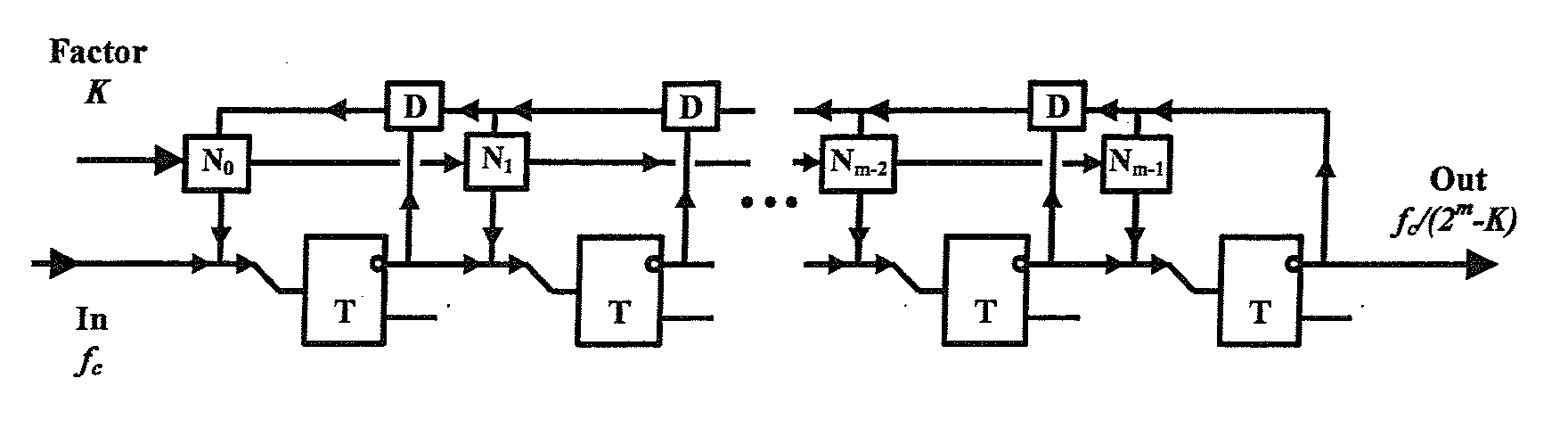
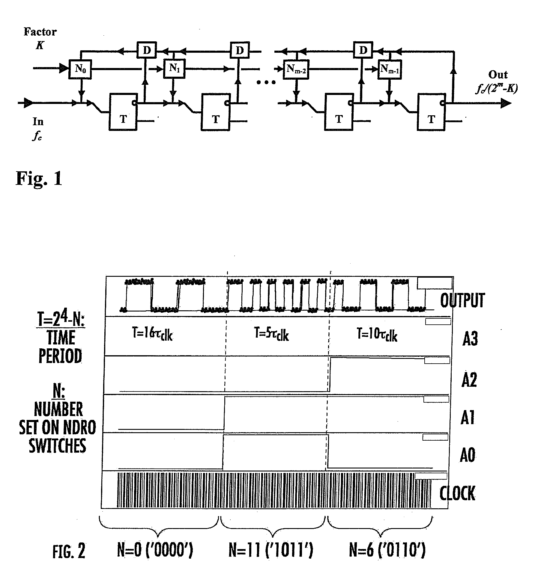
[0025]FIG. 1 is a block diagram of a digital programmable frequency divider (PFD) in accordance with one aspect of the invention. A programmable local oscillator (PLO) is a very useful part of many digital processing systems. The traditional way of producing a pulse signal of needed frequency is to divide a high-frequency reference signal by a certain factor. Previously suggested Rapid Single Flux Quantum (RSFQ) clock dividers were able to decimate only by factors of 2n. The frequency divider of the invention is capable of dividing the input signal frequency by any natural number from 1 to 2n, where n is the number of bits (the length of the circuit).

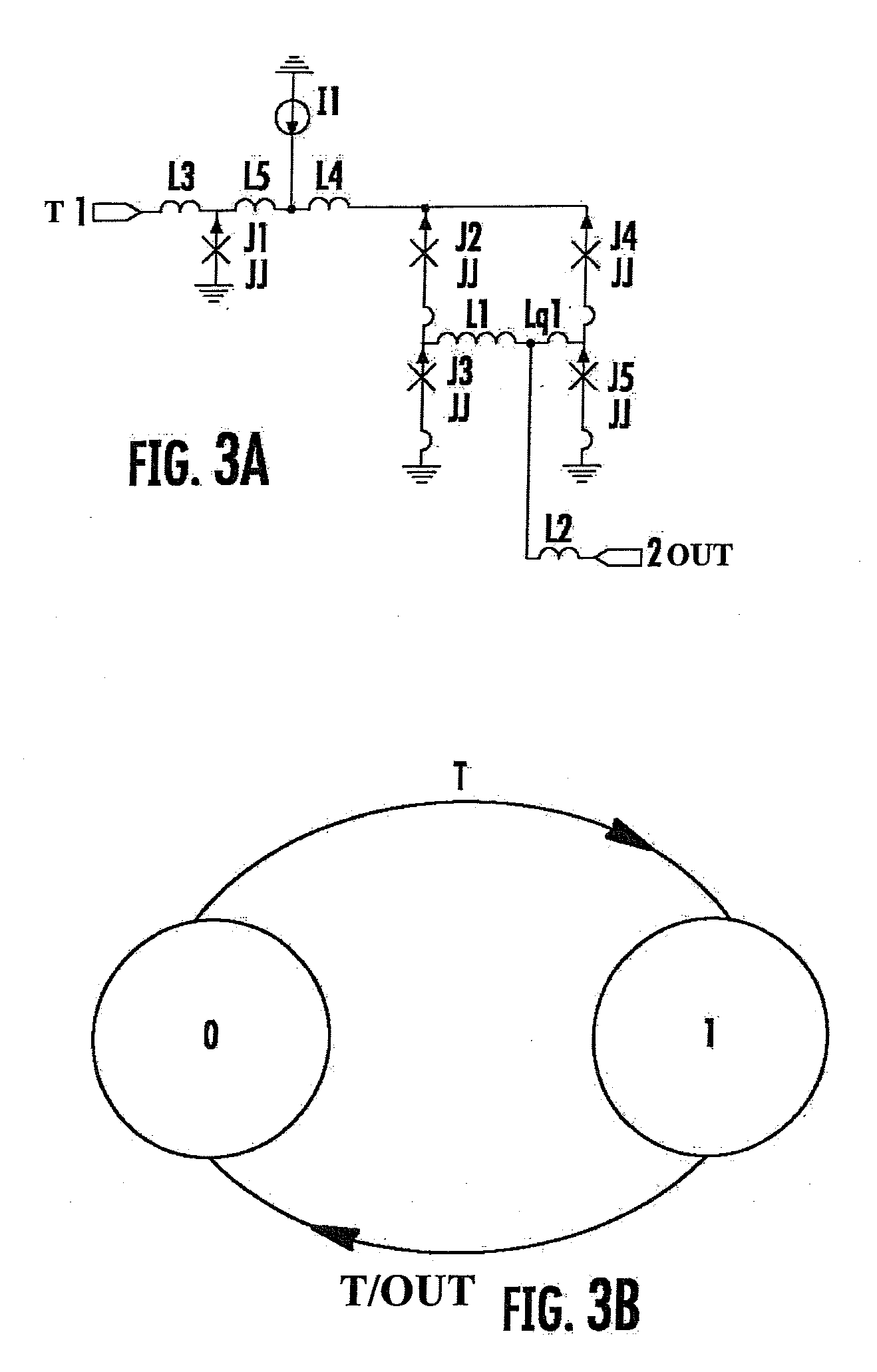
[0026]The frequency divider consists of basic RSFQ cells: T flip-flops (designated as T), D flip-flops (designated as D), and Non-Destructive Read-Out cells (NDRO) or alternative DC-driven switches (designated as K).

[0027]The functionality of the Programmable Frequency Divider is rather complex. When all n switches are OFF (digital word...


PUM


Abstract

A digital programmable frequency divider is constructed of Rapid Single Flux Quantum (RSFQ) logic elements. The logic elements may include an RSFQ non-destructive readout cell (NDRO), and RSFQ D flip-flop and an RSFQ T flip-flop. A digital word comprising N bits is used to control the amount of frequency division and the frequency divider selectively imparts a respective frequency division for any of 2N states that can be represented by the digital word. The RSFQ logic elements utilize Josephson junctions which operate in superconducting temperature domains.

Description

CROSS REFERENCE TO RELATED APPLICATIONS[0001]This application is a continuation in part of U.S. patent application Ser. No. 11 / 243,022, filed Oct. 4, 2005, entitled A Digital Programmable Frequency Divider by inventor Alexander Kirichenko, which is hereby incorporated by reference in its entirety.STATEMENT REGARDING FEDERALLY FUNDED RESEARCH[0002]This invention was made with Government support under Contract number N00014-03-C-00 awarded by the Department of the Navy. The Government has certain rights in the invention.BACKGROUND OF THE INVENTION[0003]1. Field of the Invention[0004]The invention described herein relates to the field of superconductivity, and more specifically relates to circuits and techniques for implementing a precise digital frequency divider using Josephson junctions.[0005]2. Related Art[0006]Josephson junctions are quantum-mechanical circuit elements of superconducting devices. The Josephson effect in particular results from two superconductors acting to preserv...

Claims


Application Information

Patent Timeline
IPC IPC(8): H03B19/00
CPCH03K23/763
Inventor KIRICHENKO, ALEXANDER F.
Owner SEEQC INC
Why Eureka
Try Eureka