Aperture correction for lenticular screens

a technology of autostereoscopic display and aperture correction, which is applied in the direction of instruments, sorting, coatings, etc., can solve the problems of lenticular screen, lenticular screen, and design employing lenticular screen, so as to reduce the numerical aperture and enhance the selection of images.

Active Publication Date: 2008-08-07
REAID INC
View PDF10 Cites 84 Cited by
  • Summary
  • Abstract
  • Description
  • Claims
  • Application Information

AI Technical Summary

Benefits of technology

[0014]According to a second aspect of the present design, there is provided a method for providing an enhanced image selection device. The method comprises applying an opaque overcoat material to an image selection device comprising a plurality of lenticules and removing selected portions of the opaque overcoat material from the image selection device. The applying and removing operate together with the image selection device to reduce a numerical aperture for at least one lenticule.

Problems solved by technology

In practice, designs employing lenticular autostereoscopic screens have drawbacks because they reduce the overall effective display sharpness.
Further issues with lenticular screens can occur when a multiplicity of non-primary viewing zones exist, particularly with respect to the sharpness of those non-primary viewing zones.
In practice, designs employing raster barrier displays reduce the overall display brightness and introduce undesirable visible pattern noise.
In fact, raster barrier autostereoscopic screens turn out to be so dim, typically losing 80 or 90 percent of the light when rendering multi-perspective images, that they may not be commercially viable when used with currently available flat panel displays.
Autostereoscopic displays using either lenticular screen, raster barrier, or “fly eye lens” techniques are difficult to manufacture due to the tight dimensional and alignment tolerances required when used with the underlying flat panel monitor device electronic display.

Method used


Image

  • Aperture correction for lenticular screens
  • Aperture correction for lenticular screens
  • Aperture correction for lenticular screens

Examples


Embodiment Construction

[0026]The following description and the drawings illustrate specific embodiments sufficiently to enable those skilled in the art to practice the system and method described. Other embodiments may incorporate structural, logical, process and other changes. Examples merely typify possible variations. Individual components and functions are generally optional unless explicitly required, and the sequence of operations may vary. Portions and features of some embodiments may be included in or substituted for those of others.

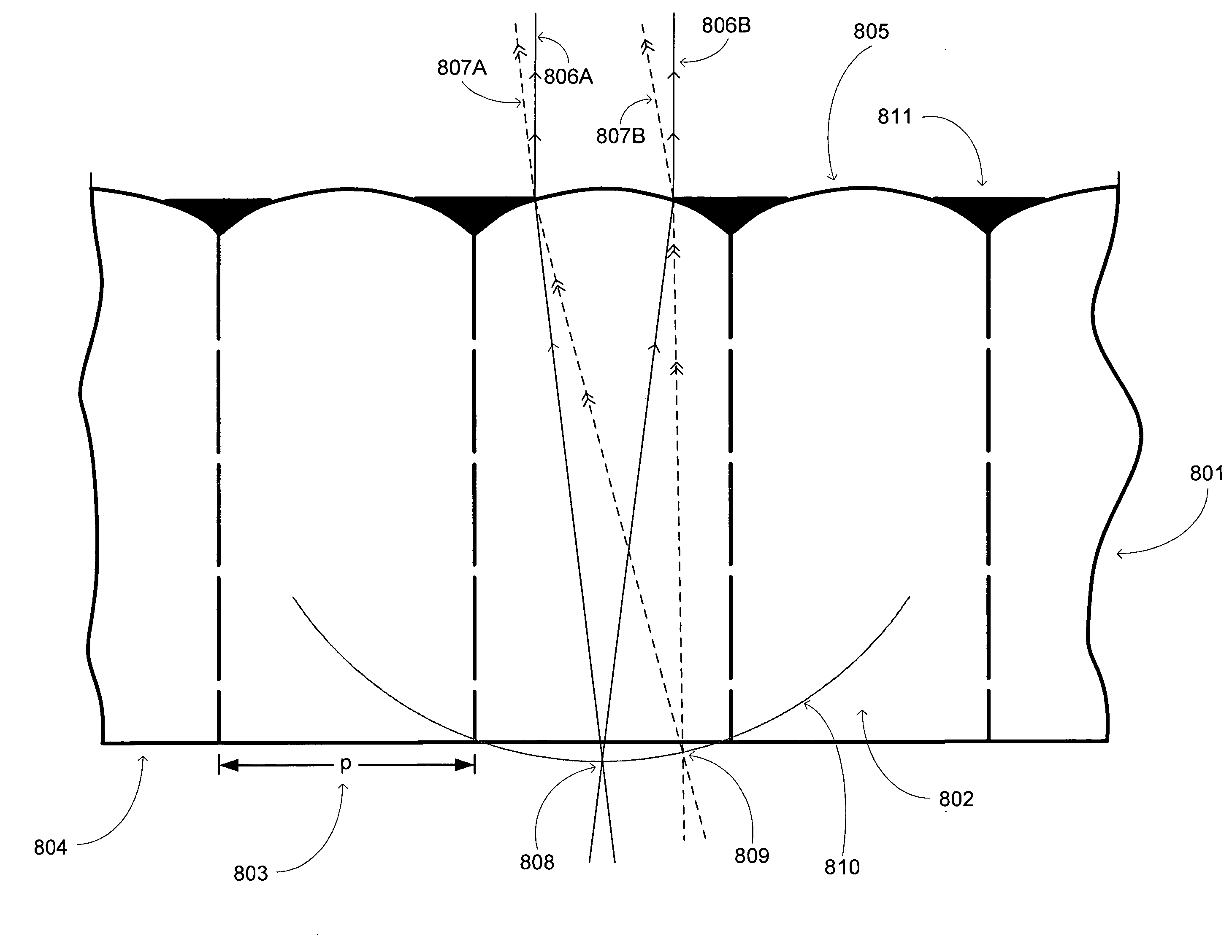
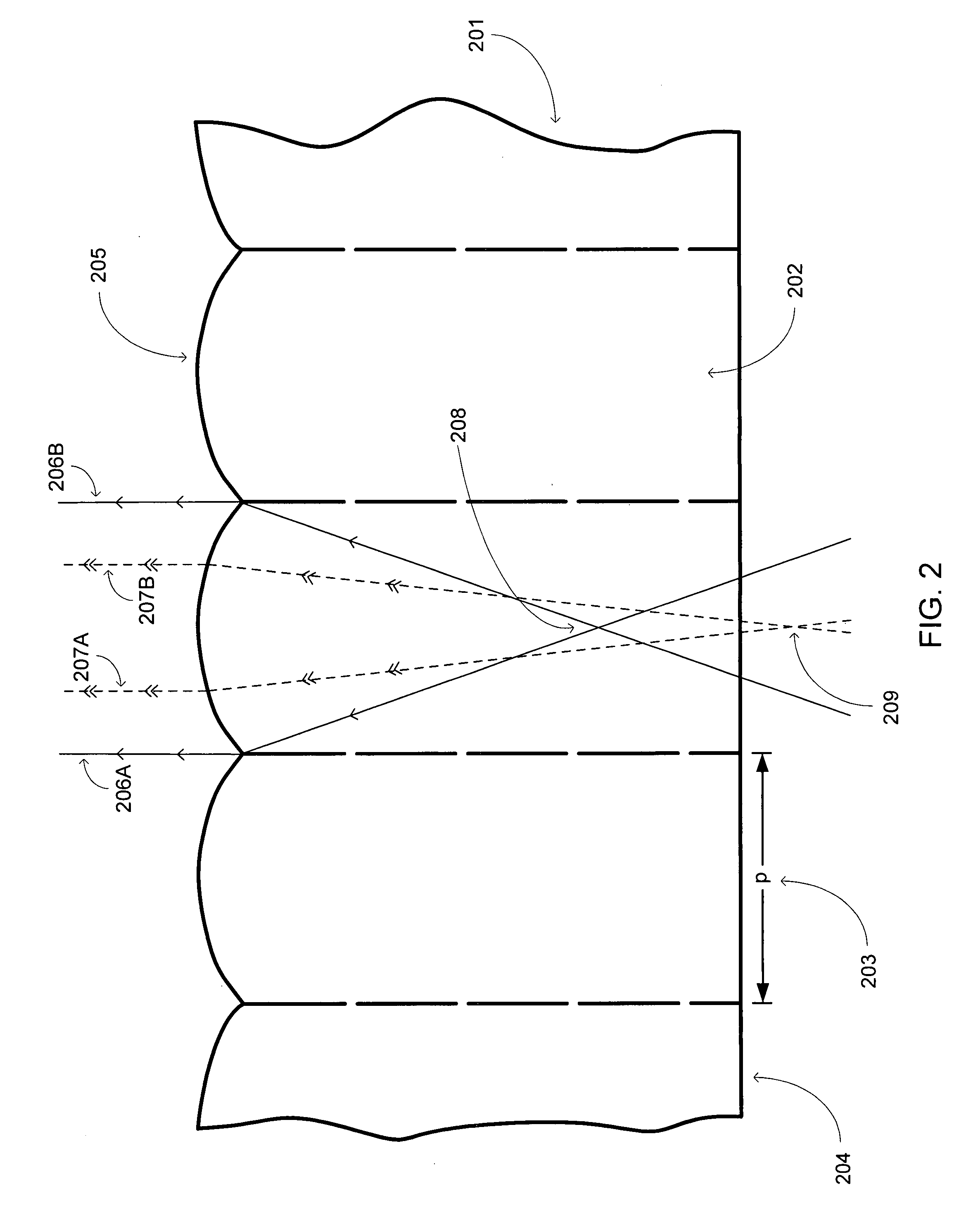
[0027]The present design combines the virtues of both refractive or lenticular autostereoscopic displays and raster barrier displays. The technique described herein vastly improves the image quality of an autostereoscopic display using refractive lenticular optics, with only a minor reduction in light output.
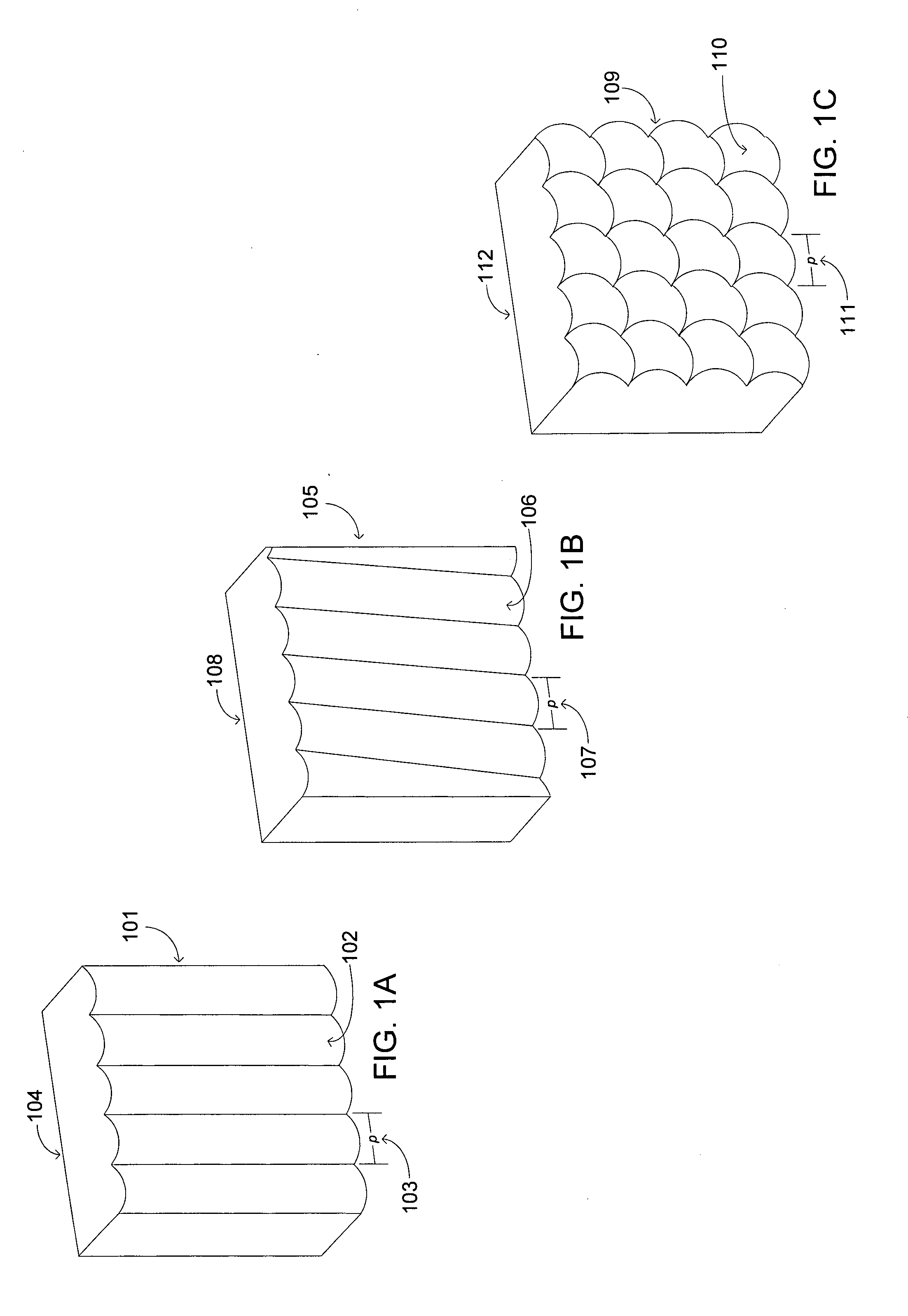
Lenticular Screens

[0028]Autostereoscopic display technology has been applied to flat panel displays with some success. There are two major variants—one using refra...


PUM


Abstract

An apparatus including an autostereoscopic image selection device and an overcoat opaque material applied to the autostereoscopic image selection device. The autostereoscopic image selection device and overcoat opaque material operate together to provide a self-locating aperture in association with the autostereoscopic selection device. The associated method entails applying an opaque overcoat material to an image selection device comprising a plurality of lenticules and removing selected portions of the opaque overcoat material from the image selection device. The applying and removing operate together with the image selection device to reduce a numerical aperture for at least one lenticule.

Description

BACKGROUND OF THE INVENTION[0001]1. Field of the Invention[0002]The present design relates generally to the art of autostereoscopic displays, and more specifically to enhanced techniques for flat panel monitor devices that improve optical quality, and increase the depth of the image and the number and quality of the viewing zones.[0003]2. Description of the Related Art[0004]Today's stereoscopic display manufacturers seek to continually improve the image quality associated with the presentation of three-dimensional (3-D) content. One current autostereoscopic flat panel monitor device that exhibits improved image quality uses refractive optic techniques for image selection. Refractive optic designs typically include lenticular screens and Winnek slanted lenses. Another current flat panel monitor design relies on raster barrier techniques for image selection. In both designs, columns of images consisting of stripes made up of perspective views form a repeating pattern on the autostereo...

Claims


Application Information

Patent Timeline
Patent Type & Authority Applications(United States)
IPC IPC(8): G02B27/22B07C5/06G02B30/29
CPCG02B3/0012G02B27/2214G02B3/0056G02B3/005G02B30/29G02B30/27
Inventor LIPTON, LENNY
Owner REAID INC
Why Eureka
Try Eureka