Side-emitting backlight system and backlit display using the same

a backlight system and side-emitting technology, applied in static indicating devices, lighting and heating apparatuses, instruments, etc., can solve the problems of large volume of calculation, which may not be desirable, and achieve the effect of reducing light interference, minimizing or reducing interferen

Inactive Publication Date: 2008-08-07
HONG KONG APPLIED SCI & TECH RES INST
View PDF6 Cites 26 Cited by
  • Summary
  • Abstract
  • Description
  • Claims
  • Application Information

AI Technical Summary

Benefits of technology

[0012]The backlight system preferably further comprising a plurality of light guides for directing light emitted from the light emission units in a direction towards the display panel. Preferably each light emission unit has associated therewith one or more light guides. The one or more light guides of each light emission unit preferably direct correspond to the corresponding region of the display panel associated with that light emission source. Preferably the light guides are arranged in a manner so as to reduce light interference between adjacent regions of the image display panel.
[0013]Each light guide may include a first side surface adjacent its corresponding group of light emitting sources for incidence of light from the corresponding group of light emitting sources into the light guide, and a second side surface through which light is emitted towards the display panel. Preferably each light guide includes a third side surface which is substantially light-impermeable for minimizing or reducing the interference between the light emission of different light emission units, and the third side surface of each light guide is substantially reflective and may be coated with substantially reflective materials. The second side surface of each light guide may be substantially diffusive.

Problems solved by technology

However, most conventional dynamic controlled backlight system may require a large volume of calculation to process the input image for the purpose of compensating the adjustment in the backlight.
Such a large volume of calculation may not be desirable.

Method used


Image

  • Side-emitting backlight system and backlit display using the same
  • Side-emitting backlight system and backlit display using the same
  • Side-emitting backlight system and backlit display using the same

Examples


Embodiment Construction

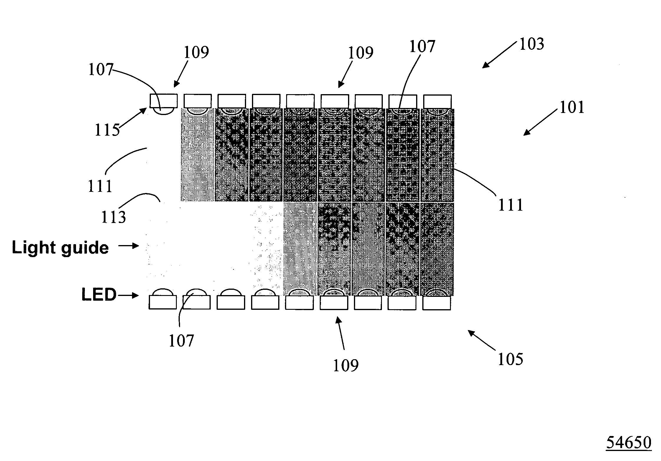
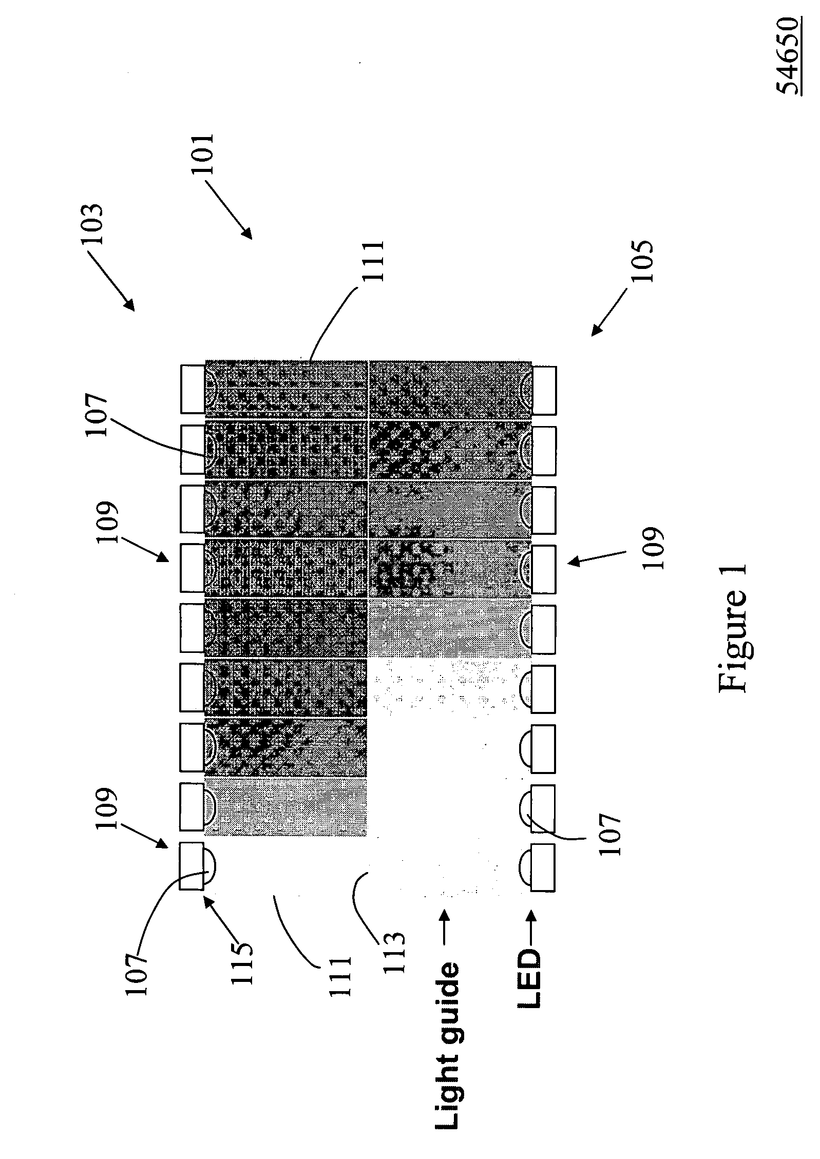
[0037]FIG. 1 illustrates an exemplary embodiment of a side-emitting backlight system 101 of the present invention suitable for use in a backlit display such as liquid crystal displays, mobile phone screens, personal digital assistant (PDA) screens, laptop monitors, personal computer monitors, and etc. The side emitting backlight system 101 includes 2 regions 103, 105, each having a plurality of light emitting diodes (LED) 107, which LEDs 107 are grouped into a plurality of blocks 109. The side-emitting backlight system 101 further includes a plurality of elongate light guides 111, each corresponding to a block of LEDs and extending substantially perpendicular to the regions 103, 105. In an exemplary embodiment, each block of LEDs may include RGB colour-separated LEDs, RGB LEDs in one package, white balanced colour separated LEDs, or blue or ultraviolet LED(s) coated with phosphor materials for downward conversions such that the light emission of each block is in white colour as will...


PUM


Abstract

A side-emitting backlight system for an image display panel, the system comprising a plurality of light emission units, each unit arranged so as to provide side light emission to region of an image display panel and having at least one light emission source; and a controller for individually controlling each light emission unit to vary at least one light characteristic of light emission from each light emission unit; wherein the at least one light characteristic is defined by determining at least one predefined parameter of light for each of a plurality of regions of an image to be displayed on the display panel, the region of the image corresponding to an adjacent light emission unit.

Description

FIELD OF THE INVENTION[0001]The present invention relates to a backlit display, more particularly to a backlit display having a dynamically controlled side-emitting backlight system.BACKGROUND OF THE INVENTION[0002]Side-emitting backlight systems are widely used in small-to-middle sized backlit display products, for example, liquid crystal displays, mobile phone screens, personal digital assistant (PDA) screens, laptop monitors, personal computer monitors, and etc. In general, a conventional side-emitting backlight system includes one or a pair of opposed regions each with a plurality of linearly arranged light emitting sources thereon for emission of light. The conventional side-emitting backlight system may also include a light guide extending perpendicular to the regions having a reflective bottom surface and an upper surface for emitting a surface light toward an upper side for the purpose of illuminating the display.[0003]In recent developments, it has been realized that in ord...

Claims


Application Information

Patent Timeline
Patent Type & Authority Applications(United States)
IPC IPC(8): F21V8/00
CPCG02B6/0068G09G2360/16G09G2320/0646G09G3/3426
Inventor HUANG, DANDINGLIU, YINGCHEN, SHOU LUNGPENG, HUAJUNNG, KWAN WAHTSAI, CHEN-JUNG
Owner HONG KONG APPLIED SCI & TECH RES INST
Why Eureka
Try Eureka