Backlight module and display apparatus

a backlight module and display device technology, applied in lighting and heating devices, instruments, static indicating devices, etc., can solve the problems of deteriorating the controlling effect of local dimming, uneasy dimming of the center region of the light guide plate, etc., to enhance the number of local dimming regions, improve the local dimming effect, and reduce light interference

Active Publication Date: 2013-09-17
TCL CHINA STAR OPTOELECTRONICS TECH CO LTD
View PDF14 Cites 4 Cited by
  • Summary
  • Abstract
  • Description
  • Claims
  • Application Information

AI Technical Summary

Benefits of technology

[0019]In comparison with the conventional local dimming method which has LED chips disposed at two sides of a light guide plate, the backlight module and the display apparatus of the present invention can comprise the light sources disposed at two sides of the stacked light guide units, wherein each of the light sources corresponds to one of the light guide units. Therefore, the light of the center region of the backlight module can be locally dimmed for improving the local dimming effect. Furthermore, the backlight module of the present invention can enhance the number of the locally dimmed regions and reduce the light interference between the different lighting regions.

Problems solved by technology

However, in this local dimming method, the lighting of a center region of the light guide plate is uneasy to be dimmed.
That is, the center region of the backlight module can not be dimmed, and the regions capable of locally dimming are fewer, thereby deteriorating the controlling effect of the local dimming thereof.

Method used


Image

  • Backlight module and display apparatus
  • Backlight module and display apparatus
  • Backlight module and display apparatus

Examples


first embodiment

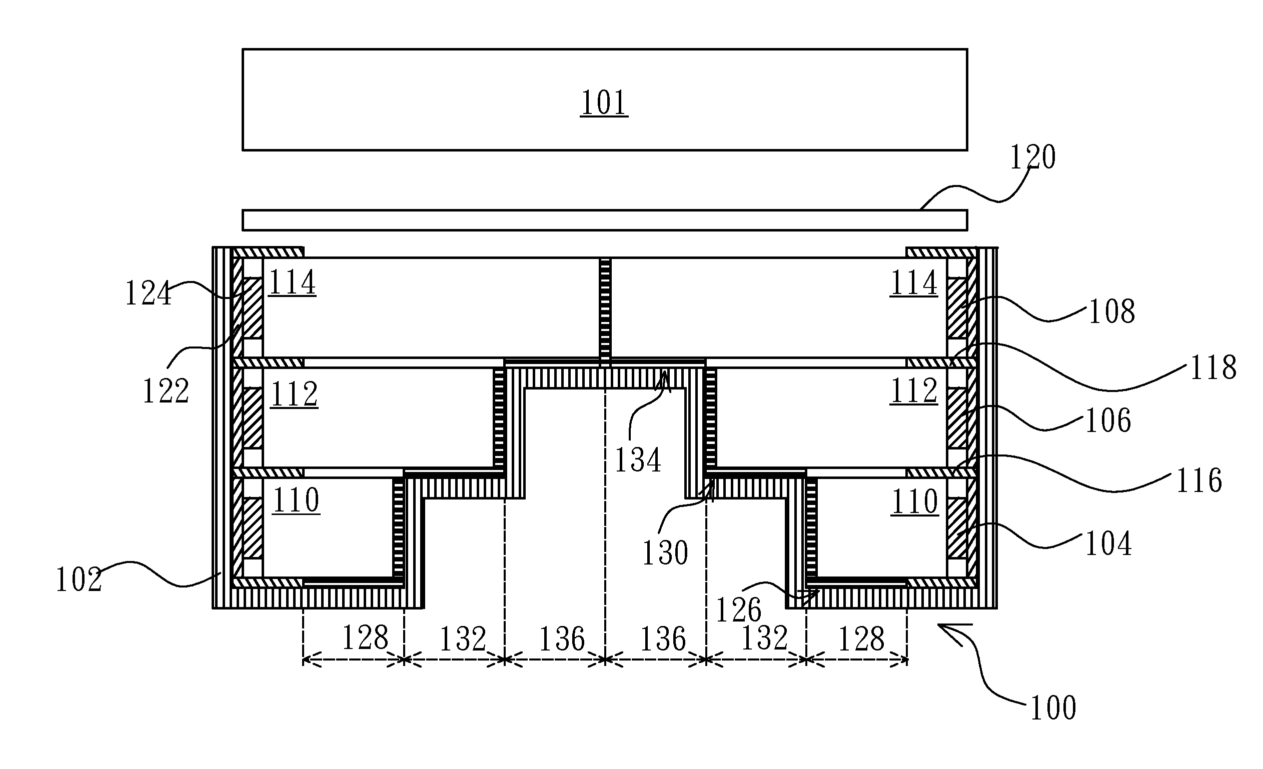
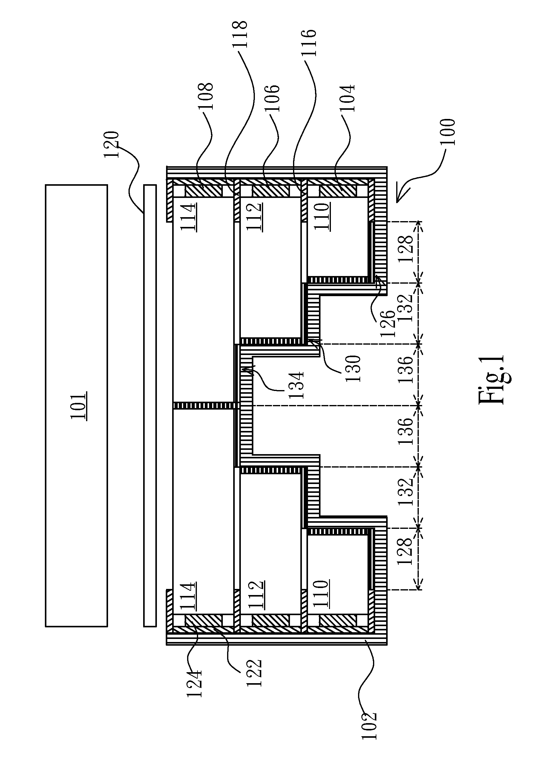
[0029]Referring to FIG. 1, a cross-sectional view showing a backlight module and a display panel according to the present invention is illustrated. The backlight module 100 of the present embodiment may be for example an edge-lighting type backlight module and disposed opposite to a display panel 101 (such as a liquid crystal display panel), thereby forming a display apparatus (an LCD apparatus). The backlight module 100 comprises a back bezel 102, a plurality of first light sources 104, a plurality of second light sources 106, a plurality of third light sources 108, a plurality of first light guide units 110, a plurality of second light guide units 112, a plurality of third light guide units 114, a first reflective layer 116, a second reflective layer 118 and at least one optical film 120. The back bezel 102 is configured to carry components of the backlight module 100. At least two of the light sources 104, 106, 108 are disposed at one side of the light guide units 110, 112, 114 t...

second embodiment

[0043]Referring to FIG. 3, a cross-sectional view showing a backlight module according to the present invention is illustrated. In this embodiment, the reflective surfaces 226, 230, 234 of the light guide units 210, 212, 214 are formed on inclined end surfaces thereof. That is, the reflective surfaces 226, 230, 234 are formed at one side of the light guide units 210, 212, 214, respectively, and there is a predetermined angle between the reflective surfaces 226, 230, 234 and the bottom surfaces of the light guide units 210, 212, 214 for reflecting the light of the light sources 104, 106, 108 to form the lighting regions 128, 132, 136 (similar to FIG. 1). At this time, the bottom structure of the back bezel 202 can correspond to the inclined surfaces of the light guide units 210, 212, 214 to be a V-shaped structure for supporting the light guide units 210, 212, 214.

third embodiment

[0044]Referring to FIG. 4A and FIG. 4B, cross-sectional views showing a backlight module according to the present invention are illustrated. In this embodiment, the light sources 104, 106, 108 are disposed at one side (referring to FIG. 4A) or two opposite sides (referring to FIG. 4B) of the back bezel 102. The light guide units 310, 312, 314 may be flat plate structures which are stacked corresponding to the light sources 104, 106, 108 and supported by the back bezel 302. The length of the light guide units 310, 312, 314 are identical. At this time, Each of the light guide units 310, 312, 314 may have one or more reflective surfaces 326, 330, 334 for reflecting the light of the light sources 104, 106, 108 correspondingly to form the lighting regions 128, 132, 136 (similar to FIG. 1).


PUM


Abstract

The present invention provides a backlight module and a display apparatus. The backlight module comprises at least two light sources; a plurality of light guide units corresponding to the light sources and disposed at one side thereof; and at least one reflective layer formed between the two adjacent light sources, wherein a portion of the reflective layer extends between two of the light guide units corresponding to the two light sources. The present invention can enhance the number of the locally dimmed regions and improve the light interference problem between the different lighting regions.

Description

FIELD OF THE INVENTION[0001]The present invention relates to a backlight module and a display apparatus, and more particularly to a backlight module and a display apparatus capable of local dimming.BACKGROUND OF THE INVENTION[0002]Liquid crystal displays (LCDs) have been widely applied in electrical products. Currently, most of LCDs are backlight type LCDs, and comprise a liquid crystal panel and a backlight module. According to the position of the light sources, the backlight module can be classified into a side-light type or a direct-light type, in order to provide LCDs with backlight sources.[0003]Currently, the backlight module of the LCD can have a plurality of lighting regions, and the brightness thereof in the different lighting regions can be adjusted. In a local dimming method, light emitting diode (LED) chips are disposed at two opposite side of a light guide plate, and the light guide plate can have different lighting regions by controlling the lighting of the different L...

Claims


Application Information

Patent Timeline
Patent Type & Authority Patents(United States)
IPC IPC(8): G09G3/36
CPCG02B6/0055G02B6/0076G02B6/0078G02B6/0088
Inventor FANG, LINDONGKUO, YICHENG
Owner TCL CHINA STAR OPTOELECTRONICS TECH CO LTD
Why Eureka
Try Eureka