Vehicle system

Active Publication Date: 2013-04-18
MURATA MASCH LTD
View PDF8 Cites 6 Cited by
  • Summary
  • Abstract
  • Description
  • Claims
  • Application Information

AI Technical Summary

Benefits of technology

[0024]This method makes it possible to measure the distance with a laser beam on one side of the traveling path with respect to a traveling vehicle in order to specify the position of the traveling vehicle, and perform communication on the other side of the traveling path in order to control the traveling vehicle. Consequently, the structure successfully minimizes

Problems solved by technology

Here, a laser beam from the range finding device and light for the communication can cause interference with ea

Method used


Image

  • Vehicle system
  • Vehicle system
  • Vehicle system

Examples


Embodiment Construction

[0032]Described below is a vehicle system according to preferred embodiments of the present invention with reference to the drawings.

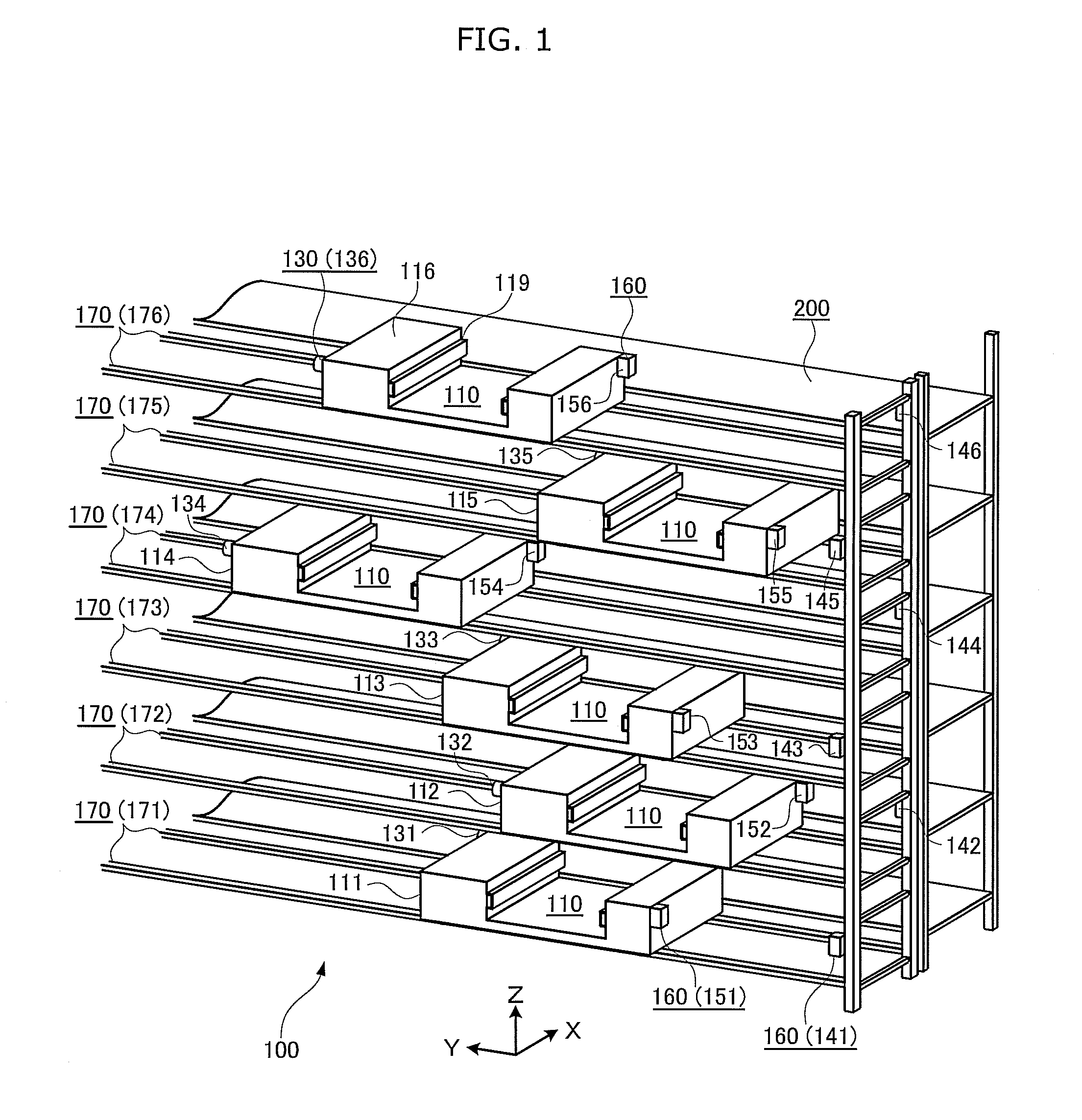
[0033]FIG. 1 depicts a perspective view which schematically shows an end of the vehicle system according to a preferred embodiment of the present invention.

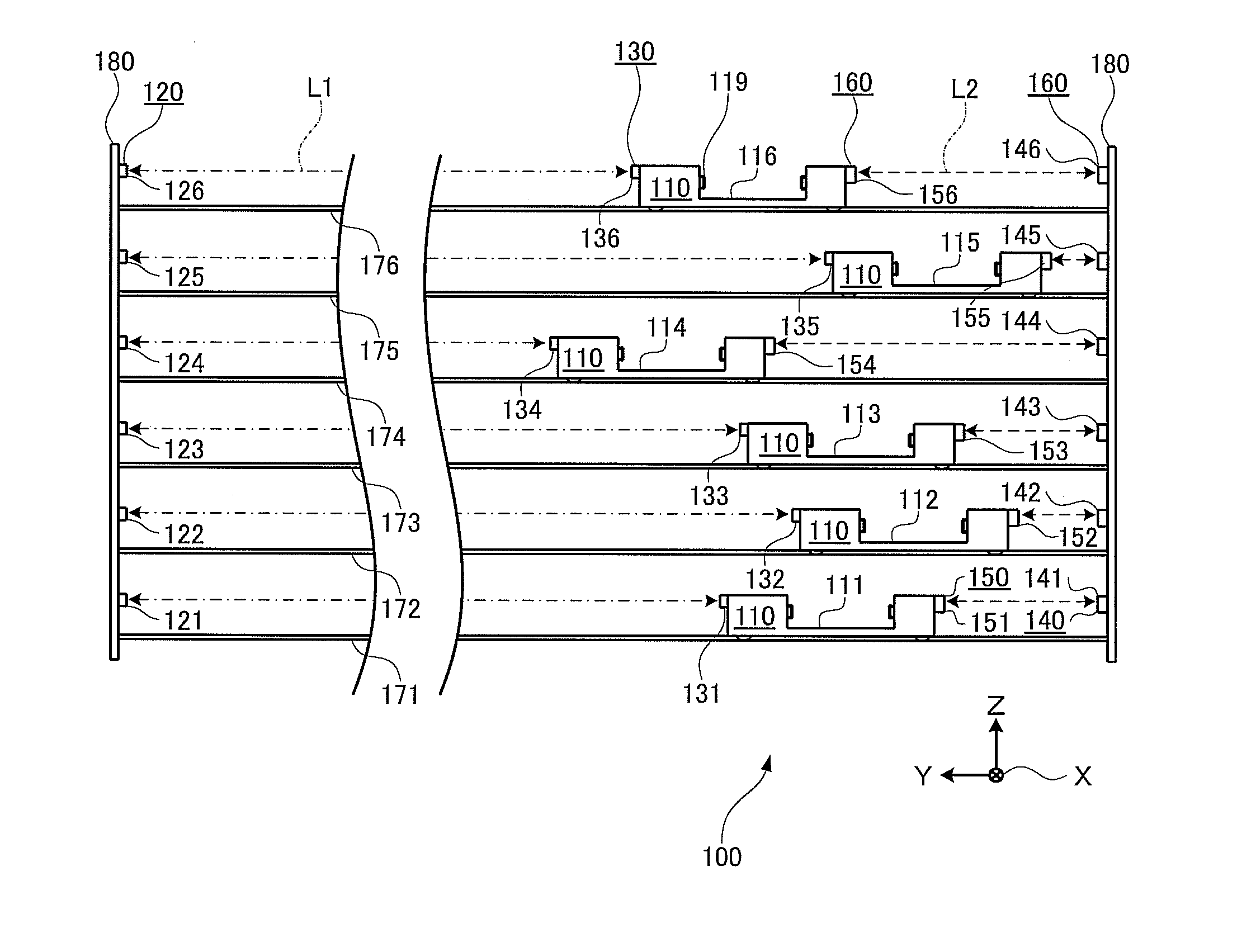
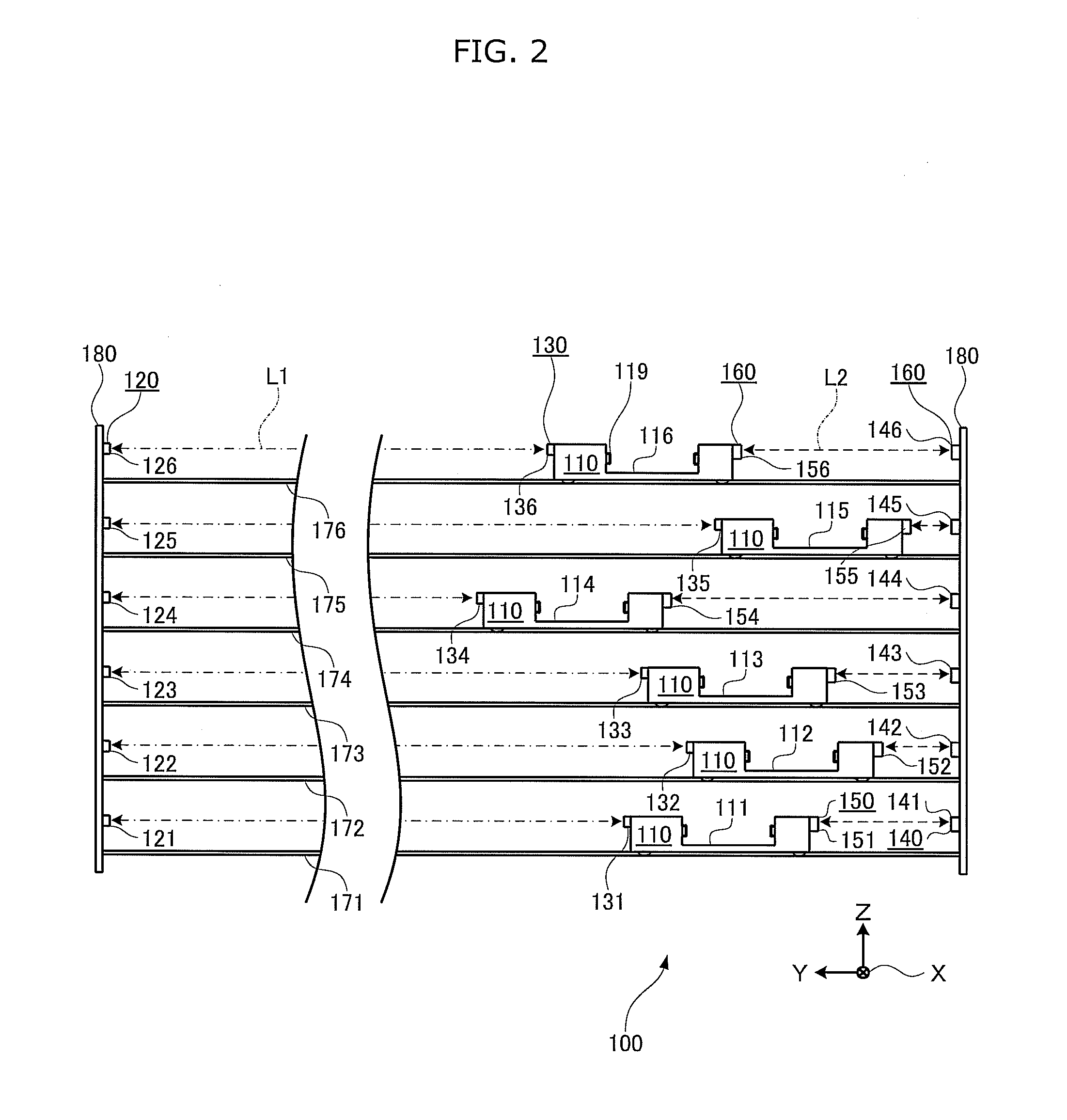
[0034]FIG. 2 depicts a plan view which schematically shows the vehicle system from the front.

[0035]The vehicle system 100 in the drawings preferably includes multiple vehicles 110 to transfer articles to a rack 200 provided along paths. The vehicle system 100 includes the vehicles 110, reflecting members 120, range finding devices 130, and communications devices 160.

[0036]Each of the vehicles 110 shuttles on a linear path. In the present preferred embodiment, the vehicle 110 shuttles along a rail 170 which defines a path extending in the y-axis direction. The vehicle 110 is equipped with a wheel and a motor (not shown) to drive the vehicle 110 itself, and includes a transfer device 119 to move an ar...


PUM


Abstract

A vehicle system includes multiple vehicles which shuttle on linear paths; a reflecting member provided on one end-side of each path; a range finding device measuring, using a laser beam, a distance between a vehicle and the reflecting member; and a communications system including a stationary communications device provided on an other end-side of the traveling path for the traveling vehicle, and performing optical wireless communication; and a mobile communications device attached to the traveling vehicle performing wireless communication with the stationary communications device.

Description

BACKGROUND OF THE INVENTION[0001]1. Field of the Invention[0002]The present invention relates to a vehicle system which includes multiple paths extending in parallel, and vehicles each shuttling on a corresponding one of the paths.[0003]2. Description of the Related Art[0004]Conventionally, there is a device to automatically load and unload multiple articles onto and from racks used for vertically and horizontally placing and storing the articles. Such a device is introduced in Japanese Unexamined Patent Application Publication No. 11-59819 as an on-rail wheeled platform system, and is also referred to as a stacker crane.[0005]The stacker crane is equipped with a transfer device to transfer an article to load and unload the article between the racks. The entire stacker crane horizontally travels along the racks, and the transfer device vertically shuttles. Such a feature makes it possible for the stacker crane to transfer an article stored on any position of the racks. Here, a posit...

Claims


Application Information

Patent Timeline
IPC IPC(8): B65G1/04G01C3/08
CPCB65G1/0421B65G1/065G01C3/08B65G1/04G05D1/02
Inventor OGAWA, KAZUHIKO
Owner MURATA MASCH LTD
Why Eureka
Try Eureka