
Video compression system

a video compression and video technology, applied in the field of video systems, can solve the problems of large storage requirements of video recording systems, inability to accurately predict frame-to-frame changes, and computationally expensive compression techniques

Inactive Publication Date: 2008-08-07
HARMAN BECKER AUTOMOTIVE SYST
View PDF6 Cites 45 Cited by
  • Summary
  • Abstract
  • Description
  • Claims
  • Application Information

AI Technical Summary

Benefits of technology

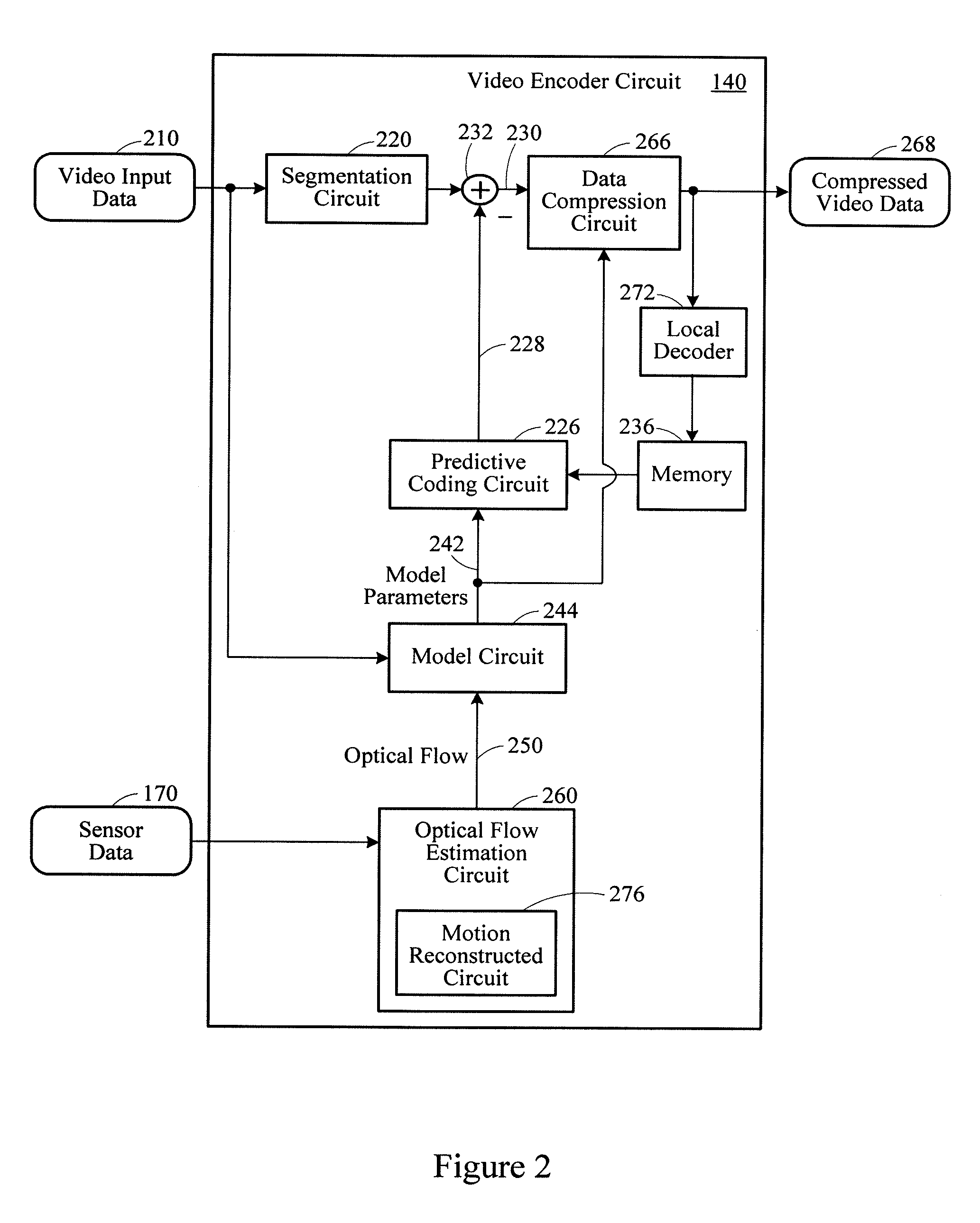
[0007]A video compression system includes a video camera mounted to a vehicle, and vehicle-mounted sensors. The vehicle-mounted sensors generate vehicle motion information corresponding to a current state of motion of the vehicle. An optical flow estimation circuit generates an estimated motion of objects within a visual field of the video camera. A video encoder circuit in communication with the optical flow estimation circuit compresses the video data from the video camera in accordance with the estimated motion.

Problems solved by technology

Vehicle video recording systems may require large amounts of storage.
However, such compression techniques may be computationally expensive and are not robust.
These compression techniques may not faithfully predict frame-to-frame changes.

Method used


Image

  • Video compression system
  • Video compression system
  • Video compression system

Examples


Embodiment Construction

[0021]Video data compression processes may reduce the bandwidth and amount of storage capacity required for transmitting and storing video data. Compression processes may be based on spatial redundancy and temporal redundancy. Spatial redundancy may relate to similarities between neighboring pixels, while temporal redundancy may relate to the similarities between consecutive frames. Spatial and temporal compression processes may reduce the amount of information saved and / or encoded. Statistical coding processes may convert data into a compressed data stream.

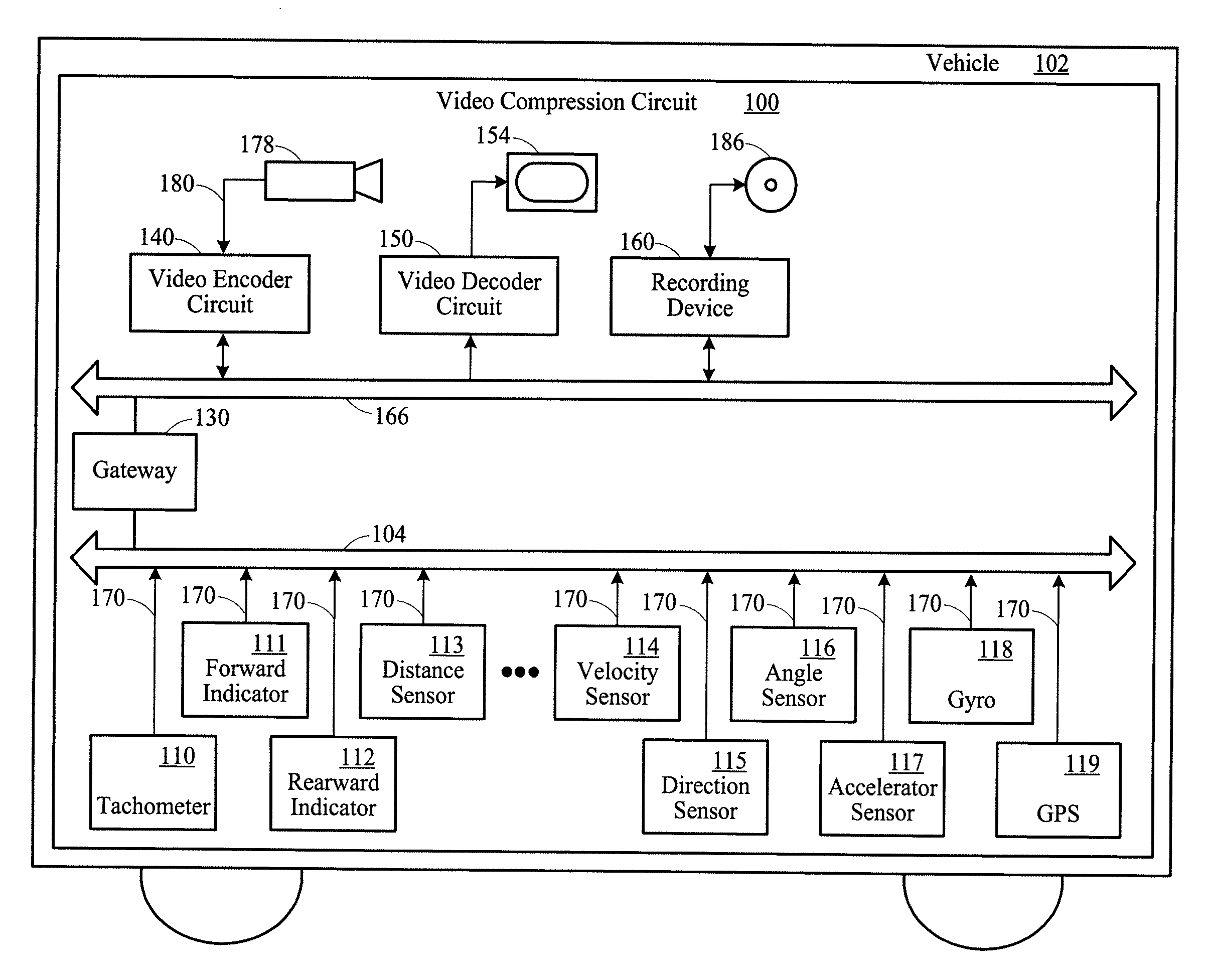
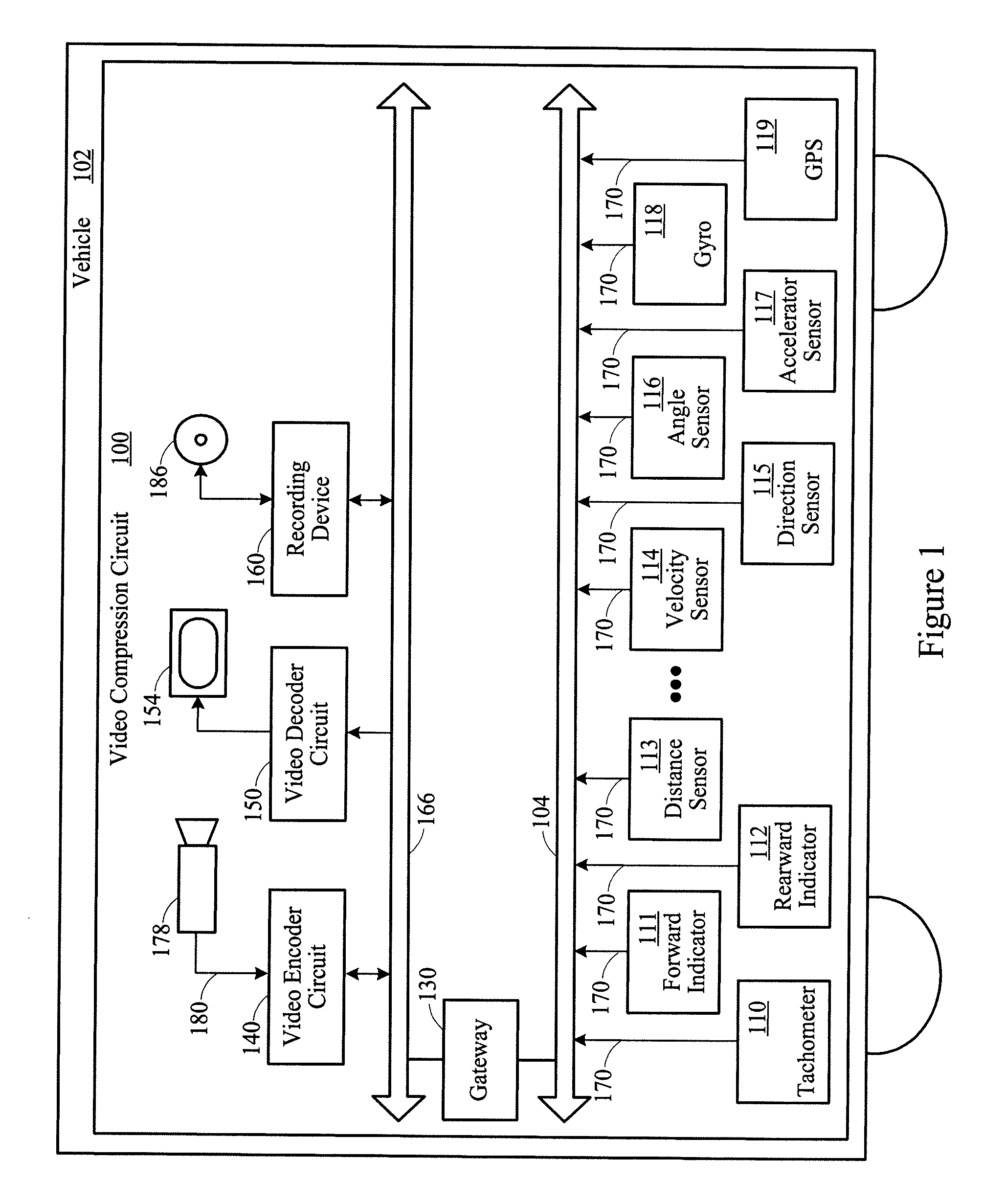
[0022]FIG. 1 is a video compression system 100. The video compression system 100 may be installed in a vehicle 102. The video compression system 100 may include a digital communication bus 104, such as a Controller Area Network (CAN) bus or a FlexRay™ bus. The digital communication bus 104 may connect a plurality of sensors 110-119 to a gateway 130.

[0023]The video compression system 100 may include multimedia components, such as ...


PUM


Abstract

A video compression system processes images captured from a video camera mounted to a vehicle. Vehicle-mounted sensors generate vehicle motion information corresponding to a current state of motion of the vehicle. An optical flow estimation circuit estimates apparent motion of objects within a visual field. A video encoder circuit in communication with the optical flow estimation circuit compresses the video data from the video camera based on the estimated apparent motion.

Description

BACKGROUND OF THE INVENTION[0001]1. Priority Claim[0002]This application claims the benefit of priority from European Patent Application No. 06 021719.7, filed Oct. 17, 2006, which is incorporated by reference.[0003]2. Technical Field[0004]This disclosure relates to video systems. In particular, this disclosure relates to video data compression systems.[0005]3. Related Art[0006]Vehicle video recording systems may require large amounts of storage. Video data may be compressed based on the differences from video frame to video frame in a pixel-oriented manner. However, such compression techniques may be computationally expensive and are not robust. These compression techniques may not faithfully predict frame-to-frame changes.SUMMARY[0007]A video compression system includes a video camera mounted to a vehicle, and vehicle-mounted sensors. The vehicle-mounted sensors generate vehicle motion information corresponding to a current state of motion of the vehicle. An optical flow estimatio...

Claims


Application Information

Patent Timeline
Patent Type & Authority Applications(United States)
IPC IPC(8): H04N7/26H04N5/00B60R21/00B60R99/00H04N5/765H04N5/92H04N19/50
CPCH04N19/61H04N19/527H04N19/137G06T7/20H04N21/414H04N19/51
Inventor STEPHAN, MARTINMOHR, ULRICH
Owner HARMAN BECKER AUTOMOTIVE SYST
Learn More