
Multi-user data transmission/reception system and mode determination method

a multi-user data and transmission/reception technology, applied in multiplex communication, orthogonal multiplex, wireless commuication services, etc., can solve the problems that the technique capable of preventing the problem of signal interference may not be applicable to a mobile station, and the multi-user communication cannot be achieved. , to achieve the effect of improving the channel capacity of multiple users

Active Publication Date: 2008-08-07
SAMSUNG ELECTRONICS CO LTD +1
View PDF12 Cites 17 Cited by
  • Summary
  • Abstract
  • Description
  • Claims
  • Application Information

AI Technical Summary

Benefits of technology

[0011]An aspect of the invention relates to a multi-user data transmission / reception system that can provide advantages of a Multiple Input Multiple Output (MIMO) system, and can also improve a channel capacity for multiple users.
[0012]An aspect of the invention also relates to a multi-user data transmission / reception system that can reduce interference occurring due to multiple users.
[0013]An aspect of the invention also relates to a multi-user data transmission / reception system that can enhance freedom of selecting a transmission mode.
[0014]An aspect of the invention also relates a multi-user data transmission / reception system that can reduce overhead and system complexity.

Problems solved by technology

Also, the multiple users cannot communicate with one another.
On a downlink channel, each of a plurality of users may receive other users' signals in addition to their own signal due to a signal interference problem that occurs because the base station simultaneously transmits signals to the plurality of users.
A technique capable of preventing the signal interference problem may not be applicable to a mobile station due to complexity and costs.

Method used


Image

  • Multi-user data transmission/reception system and mode determination method
  • Multi-user data transmission/reception system and mode determination method
  • Multi-user data transmission/reception system and mode determination method

Examples


Embodiment Construction

[0029]Reference will now be made in detail to embodiments of the invention, examples of which are shown in the accompanying drawings, wherein like reference numerals refer to like elements throughout. The embodiments are described below to explain the invention by referring to the figures.

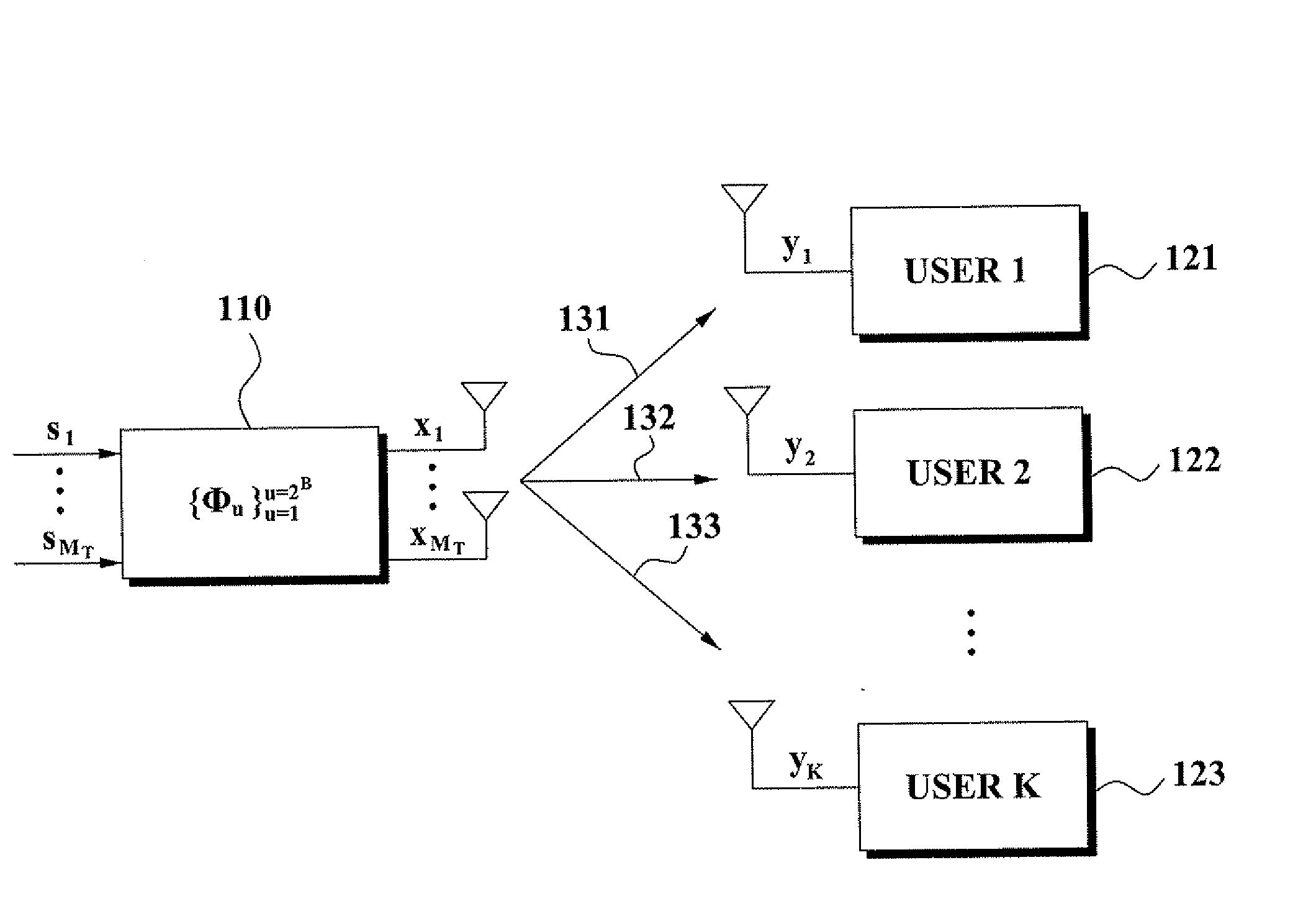
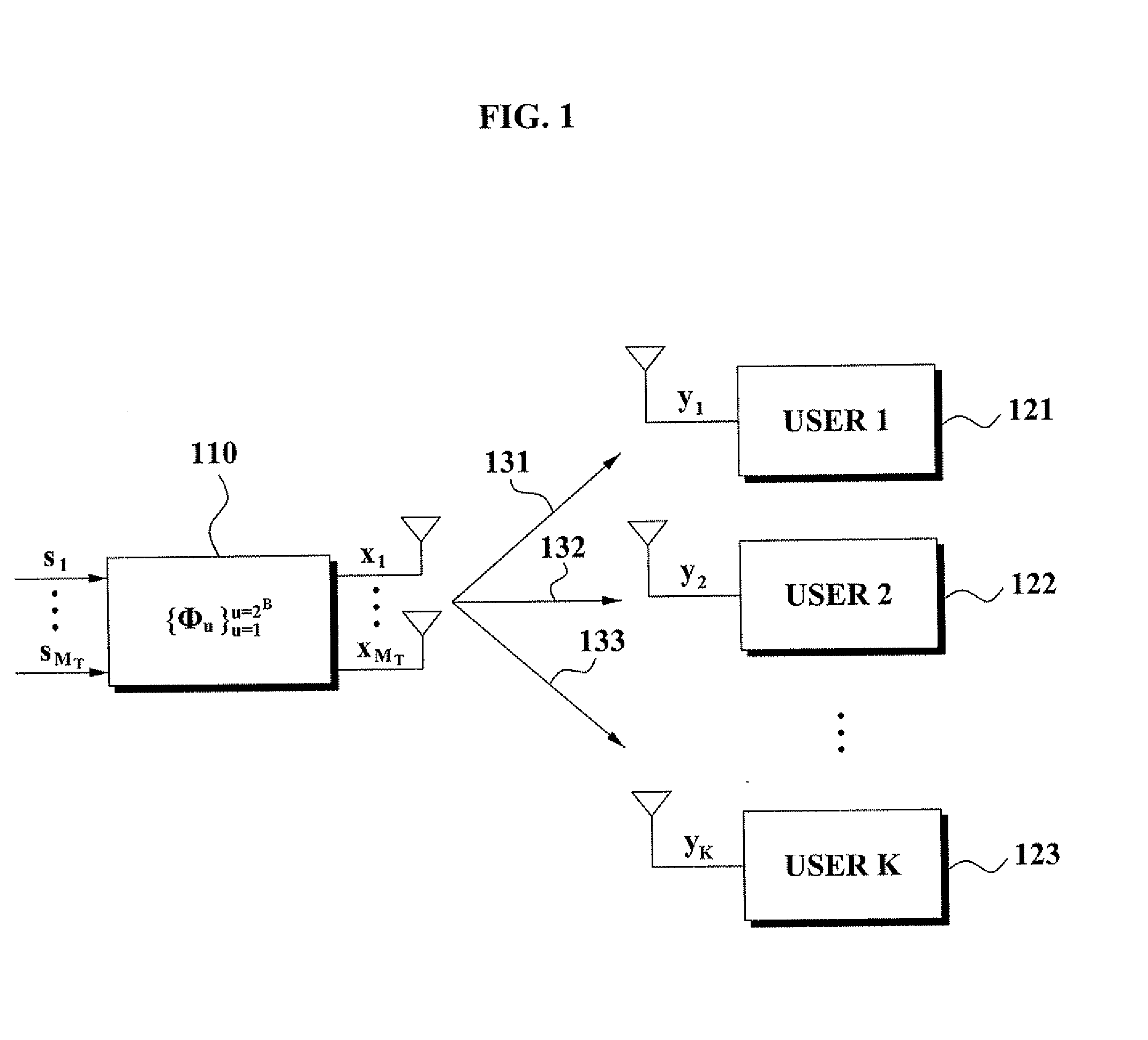
[0030]FIG. 1 is a block diagram of a data transmission / reception system according to an aspect of the invention.

[0031]Referring to FIG. 11 the data transmission / reception system according to an aspect of the invention includes mobile stations 121, 122, and 123 respectively corresponding to users 1, 2, and 3, and a base station 110.

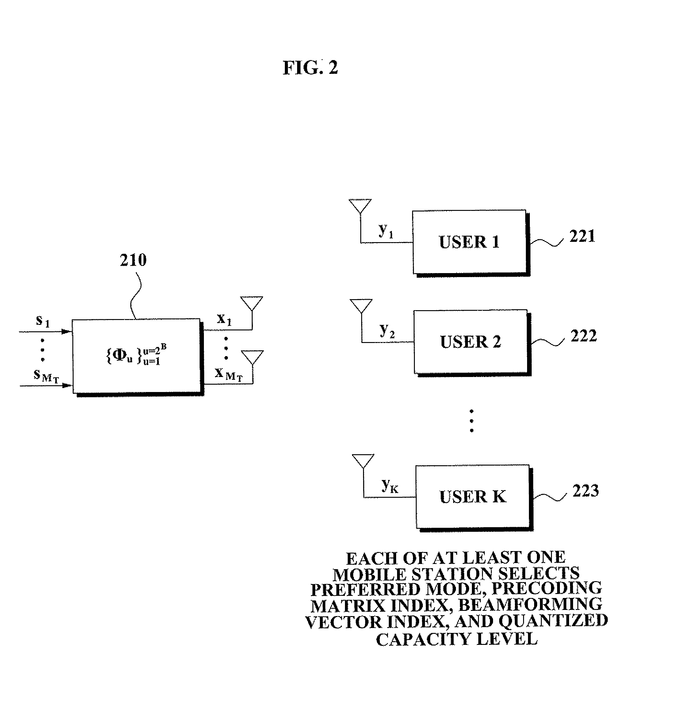
[0032]Each of the mobile stations 121, 122, and 123 selects a preferred mode, a preceding matrix index, a beamforming vector index, and a quantized capacity level using a pilot signal received from the base station 110 as indicated by arrows 131, 132, and 133, and transmits the preferred mode, the preceding matrix index, the beamforming vector index, and the quantized cap...


PUM


Abstract

A multi-user data transmission / reception system includes at least one mobile station to receive a pilot signal, select a preferred mode, a preceding matrix index, a beamforming vector index, and a quantized capacity level using the pilot signal, and transmit the preferred mode, the preceding matrix index, the beamforming vector index, and the quantized capacity level; and a base station to transmit the pilot signal to the at least one mobile station, receive the preferred mode, the preceding matrix index, the beamforming vector index, and the quantized capacity level from the at least one mobile station, and determine an optimal mode, an optimal precoding matrix, and an optimal beamforming vector using a lookup table storing an expected capacity for each capacity quantization interval.

Description

CROSS-REFERENCE TO RELATED APPLICATIONS[0001]This application claims the benefit of Korean Patent Application No. 2007-11279 filed on Feb. 2, 2007, in the Korean Intellectual Property Office, the disclosure of which is incorporated herein by reference in its entirety.BACKGROUND OF THE INVENTION[0002]1. Field of the Invention[0003]Aspects of the invention relate to a wireless data communication system. More particularly, aspects of the invention relate to a multi-user data transmission / reception system.[0004]2. Description of the Related Art[0005]Recently, various multimedia services such as a voice service are being provided in a wireless communication environment, and various studies are being conducted to support high-speed and high-quality data transmission in the wireless communication environment. For example, studies of Multiple-Input Multiple-Output (MIMO) systems using a channel in a spatial area are being conducted.[0006]A MIMO system can acquire a channel capacity using a ...

Claims


Application Information

Patent Timeline
Patent Type & Authority Applications(United States)
IPC IPC(8): H04K1/10
CPCH04B7/0452H04B7/0617H04B7/0636H04L5/0062H04B7/0689H04L5/0023H04L5/0037H04B7/0639H04B7/0456
Inventor PARK, CHANG SOONCLERCKX, BRUNOAU YEUNG, CHUN KINLOVE, DAVID J.PARK, SEUNG YOUNGKIM
Owner SAMSUNG ELECTRONICS CO LTD
Learn More