Drum unit and image forming apparatus equipped therewith

a technology of image forming apparatus and drum unit, which is applied in the direction of electrographic process apparatus, instruments, optics, etc., can solve the problems of spoiled contact between ground plates, inability to accurately perform image forming operations, and inability to reliably conduct electrical curren

Inactive Publication Date: 2008-08-07
KYOCERA DOCUMENT SOLUTIONS INC
View PDF2 Cites 4 Cited by
  • Summary
  • Abstract
  • Description
  • Claims
  • Application Information

AI Technical Summary

Benefits of technology

[0013]In view of the above circumstances, it is an object of the present invention to provide a drum unit capable of invariably obtaining reliable electrical conduction between a metal tubular member and a ground plate to remove electrostatic charges from the metal tubular member by grounding. It is another object of the present invention to provide an image forming apparatus equipped with the drum unit.

Problems solved by technology

If the metal tubular member is not adequately grounded, an electrostatic latent image is likely to be formed on the outer peripheral surface of the metal tubular member in a disordered or disarranged manner, resulting in failure of accurately performing an image forming operation.
This is likely to spoil adequate contact between the ground plate and the drum shaft, and preclude reliable electrical conduction therebetween.
This inevitably leads to an increase in the number of component parts, resulting in increase in cost.
Moreover, the Patent Publication 1 does not disclose any technical concept for obtaining reliable electrical conduction between the metal tubular member and each of the connection claws.
However, even if the distance between the respective distal ends of the opposed connection claws is set to be greater than the inner diameter of the metal tubular member by 1%, the connection claw is likely to be unable to generate an elastic force, depending on an elastically bent state of the connection claws during the course of pushing a flange member into the metal tubular member.
With inadequate elastic force by the connection claw, it is difficult to allow an inner peripheral surface of the metal tubular member to be partially cut off (i.e., scratched and scraped off) by the pointed distal ends of the connection claws in a reliable manner.
This means failure in obtaining adequate electric conduction between the metal tubular member and the ground plate.

Method used


Image

  • Drum unit and image forming apparatus equipped therewith
  • Drum unit and image forming apparatus equipped therewith
  • Drum unit and image forming apparatus equipped therewith

Examples


example 1

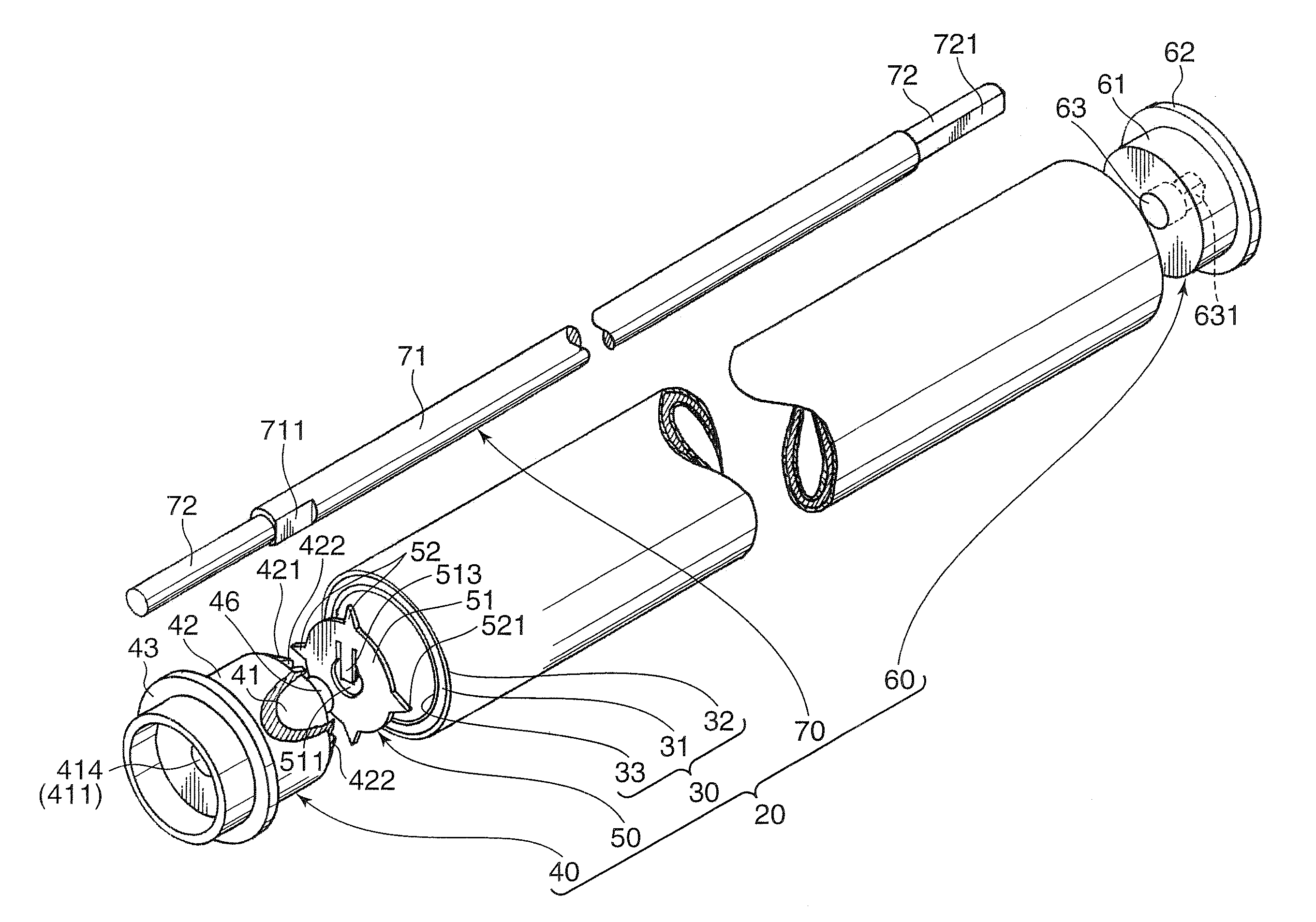
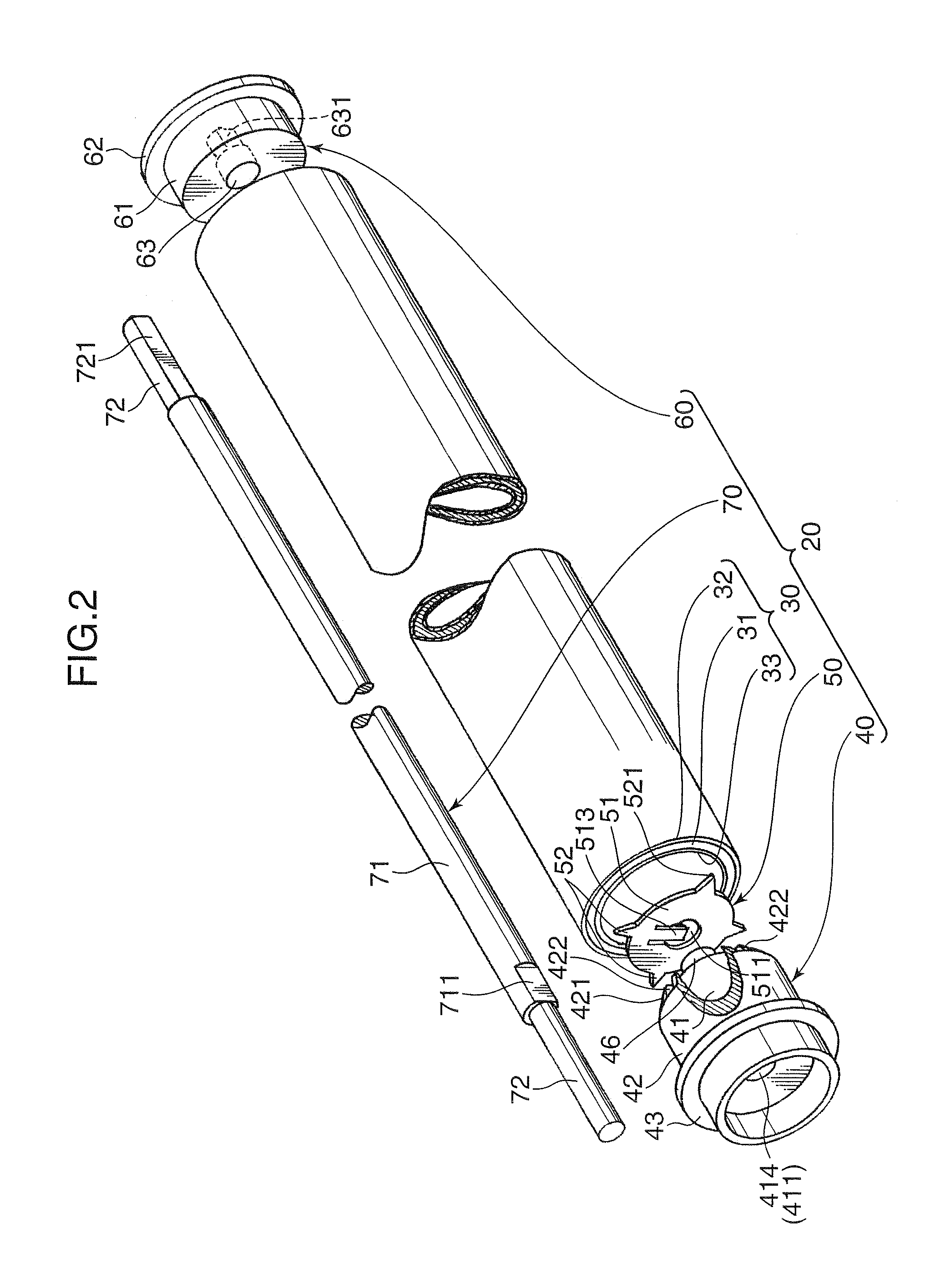
[0098]The ground plate 50 to be attached to the photosensitive drum 30 which has the outer diameter (D0 in FIG. 6A) of 24 mm and includes the metal tubular member 31 having the inner diameter (D3 in FIG. 6A) of 22.5 mm and the insulating film 33 having the thickness of 6 μm was actually prepared. After attaching the ground plate 50 inside the photosensitive drum 30 through the flange member 40, the press abutment of the pointed distal end 521 of each of the connection claws 52 against the inner peripheral surface of the photosensitive drum 30 was visually observed, and a conduction test was carried out to check electrical connection between the pointed distal ends 521 of each of the connection claws 52 and the inner peripheral surface of the metal tubular member 31.

[0099]Dimensions of the ground plate 50 were set as follows.[0100]Distance (D in FIG. 6A) between the pointed distal ends 521 of the connection claws opposed to each other in the radial direction of the ground-plate body ...

example 2

[0115]The ground plate 50 shown in the Example 1 was subjected to a test for checking a relationship between the calculational bending angle θ of the connection claw 52 and the depth of a scratch formed in the metal tubular body 31 by the connection claw 52. In this test, the outer diameter D2 of the ground-plate body 51 was changed to set the calculational bending angle θ of the connection claw 52 at various values.

[0116]After attaching each of the ground plates 50 to a flange member 40 having a bending point 412 corresponding to the calculational bending angle θ of the connection claw 52, the flange member 40 was inserted into the photosensitive drum 30. Then, the depth of a scratch formed in the metal tubular member 31 as a result of cutting off of the insulating film 33 and the photosensitive drum 30 by the pointed distal end 521 of the connection claw 52 was measured by a three-dimensional interference microscope (Model No. Wyko-NT-1100 produced by Japan Veeco Instruments Inc.)...


PUM


Abstract

A drum unit (20) for forming a toner image includes a cylindrical-shaped metal tubular member (31), a flange member (40) attached to one end of the metal tubular member (31) and a ground plate (50) attached to the flange member (40) and having an outer peripheral edge formed with a connection claw (52) that is so bent by the inner peripheral surface of the metal tubular member (31) as to bite into the inner peripheral surface for establishment of electrical conduction between the metal tubular member (31) and the ground plate (50). The flange member (40) has an edge, and the bending of the connection claw is carried out about a support point (412) defined by the edge. A calculational bending angle (θ) at which the connection claw (52) is bent about the support point (412) is set in the range of 10 to 45 degrees.

Description

BACKGROUND OF THE INVENTION[0001]1. Field of the Invention[0002]The present invention relates to a drum unit for forming a toner image based on image data, and an image forming apparatus equipped with the drum unit.[0003]2. Description of the Related Art[0004]Generally, an image forming apparatus such as a copy machine, a printer or a facsimile machine includes a metal tubular member commonly called “photosensitive drum”, in which an outer peripheral surface of the metal tubular member is irradiated with light based on image data obtained through reading or image data transmitted from outside to form an electrostatic latent image thereon, and toner is supplied from a development unit to the electrostatic latent image to develop a toner image. The toner image is transferred onto a sheet. The metal tubular member is assembled and unitized with other associated components to form a drum unit.[0005]Heretofore, the drum unit has been known such as disclosed, for example, in JP 10-319783A...

Claims


Application Information

Patent Timeline
Patent Type & Authority Applications(United States)
IPC IPC(8): G03G15/08
CPCG03G15/751
Inventor WATANABE, YUKIMASAKUBOSHIMA, SHIHOHAZAMA, HIROYUKIHAMASAKI, KAZUNARISAITO, SAKAE
Owner KYOCERA DOCUMENT SOLUTIONS INC
Why Eureka
Try Eureka