Portable Blower

a blower and portability technology, applied in the direction of positive displacement liquid engines, piston pumps, liquid fuel engines, etc., can solve the problems of reducing the resistance to flow downstream of the axial fan, increasing the blowing capacity, etc., to achieve the effect of enhancing the resistance to flow and avoiding rotational symmetry

Active Publication Date: 2008-08-14
ANDREAS STIHL AG & CO KG
View PDF7 Cites 10 Cited by
  • Summary
  • Abstract
  • Description
  • Claims
  • Application Information

AI Technical Summary

Benefits of technology

[0014]The arrangement of at least one handle means on a guide tube disposed between the engine housing and the blower unit permits an ergonomic operation. The weight of the drive motor acts at one end of the guide tube, and the weight of the blower unit acts at the other end. As a result, the blower is counterbalanced about the region of the handle means, thus enabling an ergonomic, energy-saving operation. The guide tube furthermore dictates a spacing between engine housing and blower housing, so that the intake surface of the blower unit is also spaced from the engine housing and is not partially covered by the engine housing. As a result, during intake the resistance to flow can be reduced, hence increasing the power of the blower. The relatively long guide tube between engine housing and blower housing additionally enables the blower tube to be shorter. This also reduces the resistance to flow downstream of the axial fan, and thus increases the blowing capacity. In this connection, engine housing denotes housing parts, such as covers and guards, that at least partially cover the drive motor and components driven by the drive motor. Further in this connection, the engine housing must not be a closed housing, but rather can also have an open configuration over large portions thereof.
[0015]The length of the guide tube between the engine housing and the blower housing advantageously corresponds at most to four times the length of the blower tube of the blower unit. As a result, an adequate nozzle effect can be achieved at the blower tube. At the same time, in this way a balanced weight distribution can be achieved at the handle means. To enable an ergonomic guidance of the blower, a handle means secured to the guide tube can in particular be embodied as a U-handle. A second handgrip is advantageously secured to the guide tube, with at least one control element for the drive motor being disposed thereon. As a result, the operator can grasp the motor with both hands at the guide tube. To enable an ergonomic operation, it is also possible to secure to the guide tube a control handle having a first handgrip and a second handgrip. As a result, the blower can be easily guided with two hands. At least one control element, in particular the throttle trigger of the drive motor, is advantageously disposed on one of the handgrips.
[0016]The blower unit can be detachably held on the guide tube via a coupling unit. As a result, it is easily possible to remove or replace the blower unit. In addition, the blower can be easily disassembled for transport. The motor unit can advantageously be connected to various tool fixtures via the coupling unit. As a result, the motor unit can be used in many different ways. For the operation of different tool fixtures, such as a power sweeper, a hedge trimmer, a pole pruner, or the like, only a single motor unit is required that can be connected to the respectively required tool fixture.
[0017]A reliable connection can be easily ensured if the blower unit has a connector that cooperates with the coupling unit, whereby the connector has an axial length of at least 40 mm.
[0019]The drive motor is advantageously an internal combustion engine. In this connection, the drive motor is in particular a two-cycle engine or a mixture-lubricated four-cycle engine. Favorable conditions result if the length of the axial fan is approximately 0.3 to 1.5 times the length of the blower tube. The blower tube is advantageously rotationally symmetrical relative to the axis of rotation of the axial fan. This results in symmetrical flow conditions in the blower tube, and turbulence or the like, which can lead to an increase of the resistance to flow, can be largely avoided.
[0020]The axial fan advantageously has at least one fan wheel driven by the drive shaft, and at least one guide wheel fixedly disposed in the blower housing. In this connection, the fan wheel and the guide wheel in particular form one stage of the axial fan. All of the fan wheels and all of the guide wheels of the axial fan, where a multi-stage configuration of the axial fan is provided, are expediently respectively identical to one another. This results in a straightforward construction, and the number of the different components required during manufacture is reduced. A further simplification of the manufacture is achieved if the blower housing has at least two identical housing sections, and is advantageously divided approximately parallel to the axis of rotation of the axial fan. In this connection, within manufacturing tolerances the division is advantageously exactly parallel to the axis of rotation of the axial fan. As a result, the fan wheels and the guide wheels of the axial fan can easily be installed in the housing. The axial fan can be placed into one housing section and can subsequently be closed off by one or more further housing sections. It is thereby possible to avoid having to insert the axial fan in the longitudinal direction of the blower.

Problems solved by technology

This also reduces the resistance to flow downstream of the axial fan, and thus increases the blowing capacity.

Method used


Image

  • Portable Blower
  • Portable Blower
  • Portable Blower

Examples


Embodiment Construction

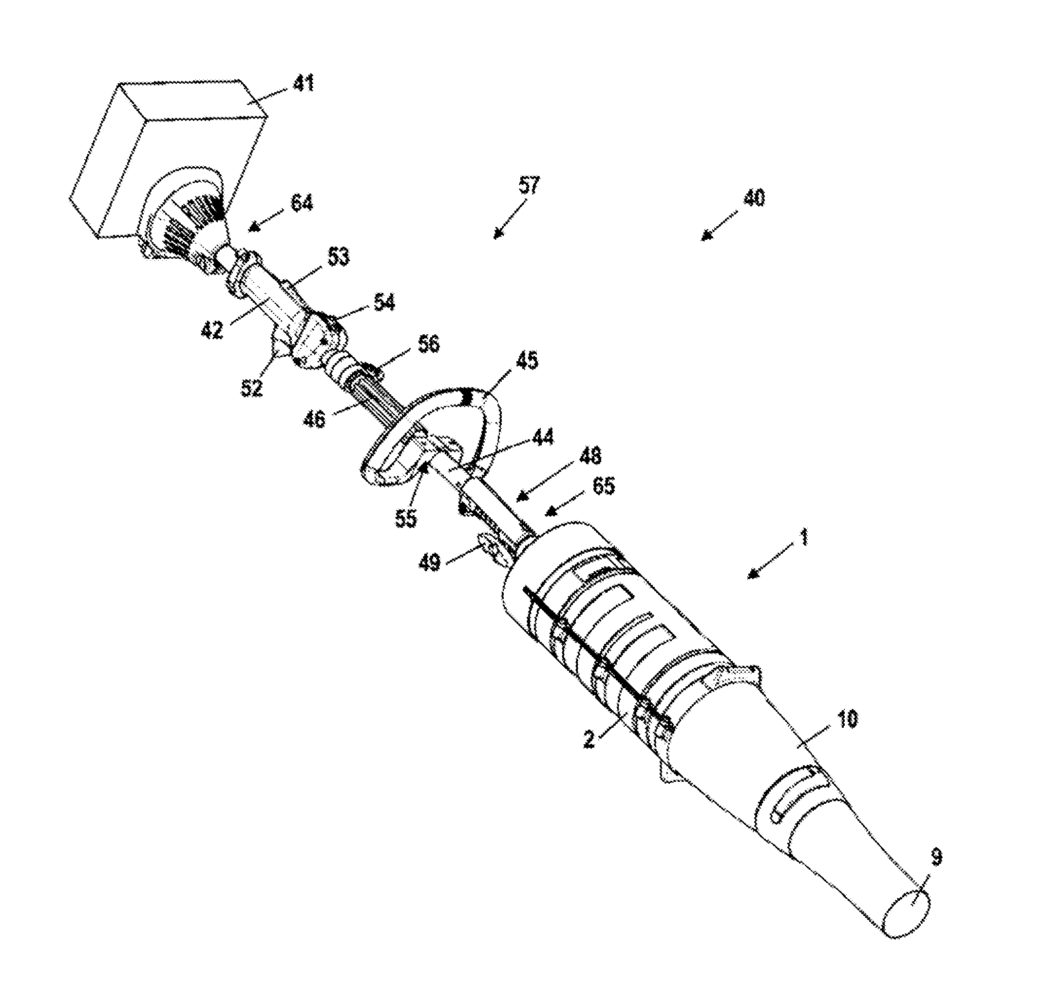
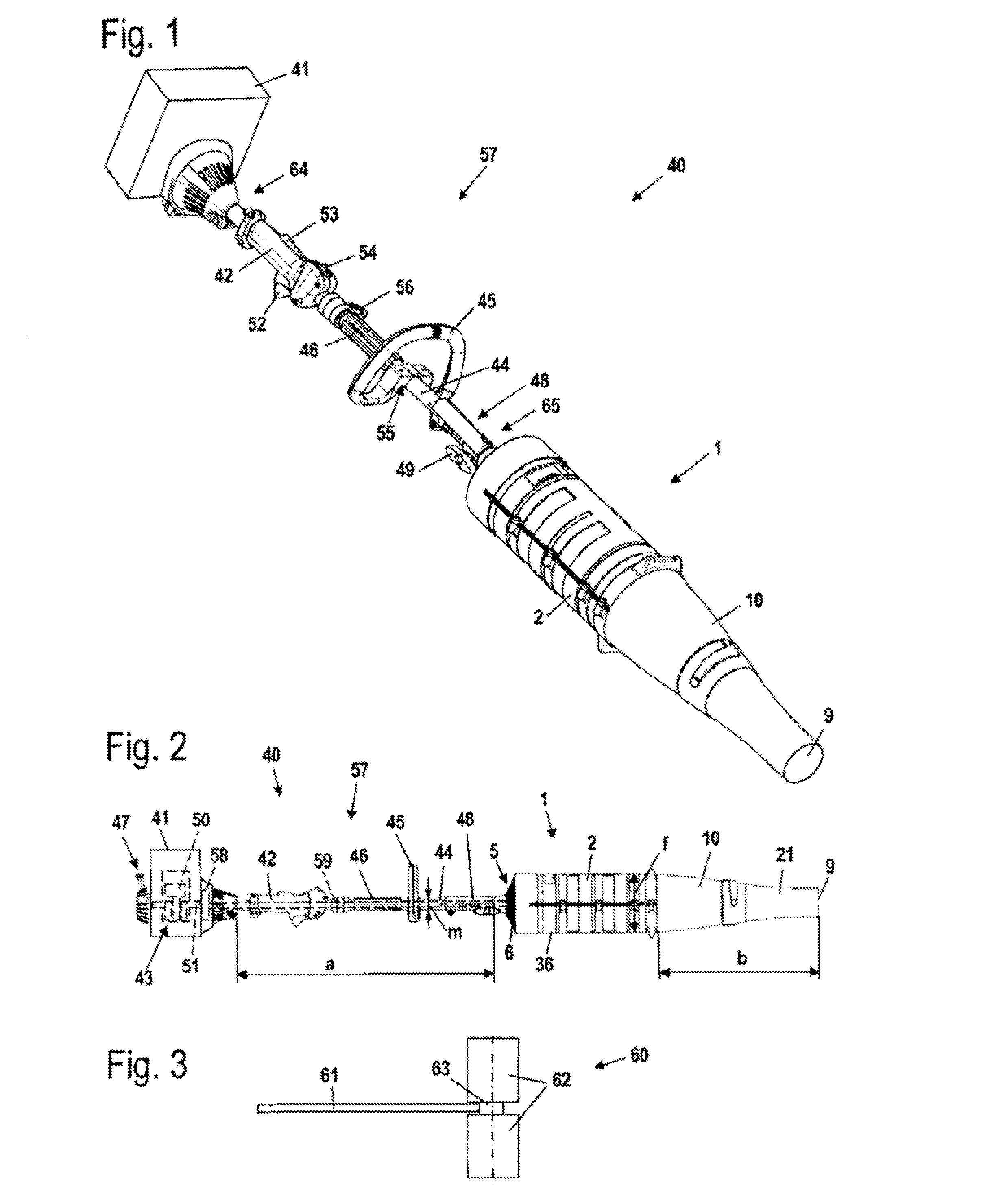
[0022]Referring now to the drawings in detail, the portable blower 40 shown in FIG. 1 has a blower unit 1 and a motor unit 57. The blower unit 1 is secured to a coupling unit 48 of the motor unit 57. The blower unit 1 is detachably held on the motor unit 57. An actuating screw 49 is provided on the coupling unit 48 for detachment of the blower unit 1.

[0023]The motor unit 57 includes an engine housing 41 and a guide tube 44 that is secured to the engine housing 41. In the illustrated embodiment, the engine housing 41 is schematically illustrated as a closed engine housing. However, the engine housing 41 can also be largely open, and can, for example, be formed by only a single cover element, so that a drive motor disposed in the engine housing 41 is substantially freely accessible from the outside. A first end 64 of the guide tube 44 is secured to the engine housing 41, and the coupling unit 48, via which the guide tube 44 is connected to the blower unit 1, is disposed at the opposit...


PUM


Abstract

A portable blower having a motor unit that includes a drive motor disposed in an engine housing. The blower has a blower unit that is provided with a blower housing that is separate from the engine housing. The blower unit includes an axial fan that is driven by the drive motor via a drive shaft. During operation the axial fan conveys operating air in the direction of the axis of rotation of the axial fan through a blower tube disposed downstream of the axial fan. An ergonomic operation and a good operating result can be achieved if the motor unit includes a guide tube on which is secured at least one handle. The engine housing is disposed at one end of the guide tube and the blower unit is disposed at the other end of the guide tube. The drive shaft extends through the guide tube. The length of the guide tube between the engine housing and the blower unit corresponds to at least half of the length of the blower tube.

Description

[0001]The instant application should be granted the priority date of Aug. 10, 2006 the filing date of the corresponding German patent application DE 10 2006 037 460.6.BACKGROUND OF THE INVENTION[0002]The present invention relates to a portable blower.[0003]U.S. Pat. No. 4,413,371 discloses a portable blower having a motor unit and a blower unit. The blower unit has an axial fan that is disposed directly adjacent to the motor unit. A long blower tube extends to the ground from the fan. Operating air is drawn in via a gap between the blower tube and the drive motor and via openings in the upper side of the blower tube.[0004]It is an object of the present invention to provide a portable blower with which a good cleaning result can be achieved and which enables ergonomic operation.BRIEF DESCRIPTION OF THE DRAWINGS[0005]This object, and other objects and advantages of the present invention, will appear more clearly from the following specification in conjunction with the accompanying sch...

Claims


Application Information

Patent Timeline
Patent Type & Authority Applications(United States)
IPC IPC(8): A47L5/14F04B35/00A47L5/12A47L9/32
CPCF04D25/02E01H1/0809F04D19/007F04D29/646
Inventor SCHLIEMANN, HARALDRABIS, MANFREDHIRT, DANIEL
Owner ANDREAS STIHL AG & CO KG
Why Eureka
Try Eureka