
Method and Machine for Making Fuel Pellets

a technology of fuel pellets and machines, applied in the direction of solid fuels, shaping presses, petroleum industry, etc., can solve the problems of reducing affecting the service life of the fuel pellet, so as to reduce the stroke length instead of the stroke length, the effect of counteracting the variation of frictional for

Inactive Publication Date: 2008-08-14
MINIPELL
View PDF2 Cites 10 Cited by
  • Summary
  • Abstract
  • Description
  • Claims
  • Application Information

AI Technical Summary

Benefits of technology

[0008]According to a second aspect of the invention, the stroke length is instead decreased as a function of operating time, thereby counteracting variations in the frictional force that arises when the material is pressed through the passage. Thereby, the stroke length can be decreased as a function of the total operating time, but the stroke length can also be decreased as a function of operating time after the last production stop.
[0009]The invention also relates to a machine for making fuel pellets. The machine according to the invention comprises a female part having at least one elongated through passage that preferably comprises at least one converging section. The machine also comprises a male part in the form of a piston arranged to conduct operating strokes in the elongated passage, and at least one force-giving member in order to give the reciprocating movement of the piston. The stroke length of the piston is variable. The machine may then be arranged to decrease the stroke length of the piston as a function of operating time, thereby counteracting variations in the frictional force that arise when the material is pressed through the passage. The machine may also be arranged to conduct a last piston stroke before shut-off, having a longer stroke length than the stroke immediately preceding it.

Problems solved by technology

Chips and shavings however have a tendency to sinter in an incinerator.
If the pellets are loose and friable, problems may arise when feeding in a pellets burner.
A known problem in connection with pellets production in which a piston presses material through an elongated passage, is that plugs may form in connection with production stops.
In connection with long stops, material remaining in the elongated passage after the last stroke of the piston may form a plug that can cause problems when production is resumed.
Sometimes, production stops may however be considerably longer than 30 minutes, whereby plugs may form.

Method used


Image

  • Method and Machine for Making Fuel Pellets
  • Method and Machine for Making Fuel Pellets
  • Method and Machine for Making Fuel Pellets

Examples


Embodiment Construction

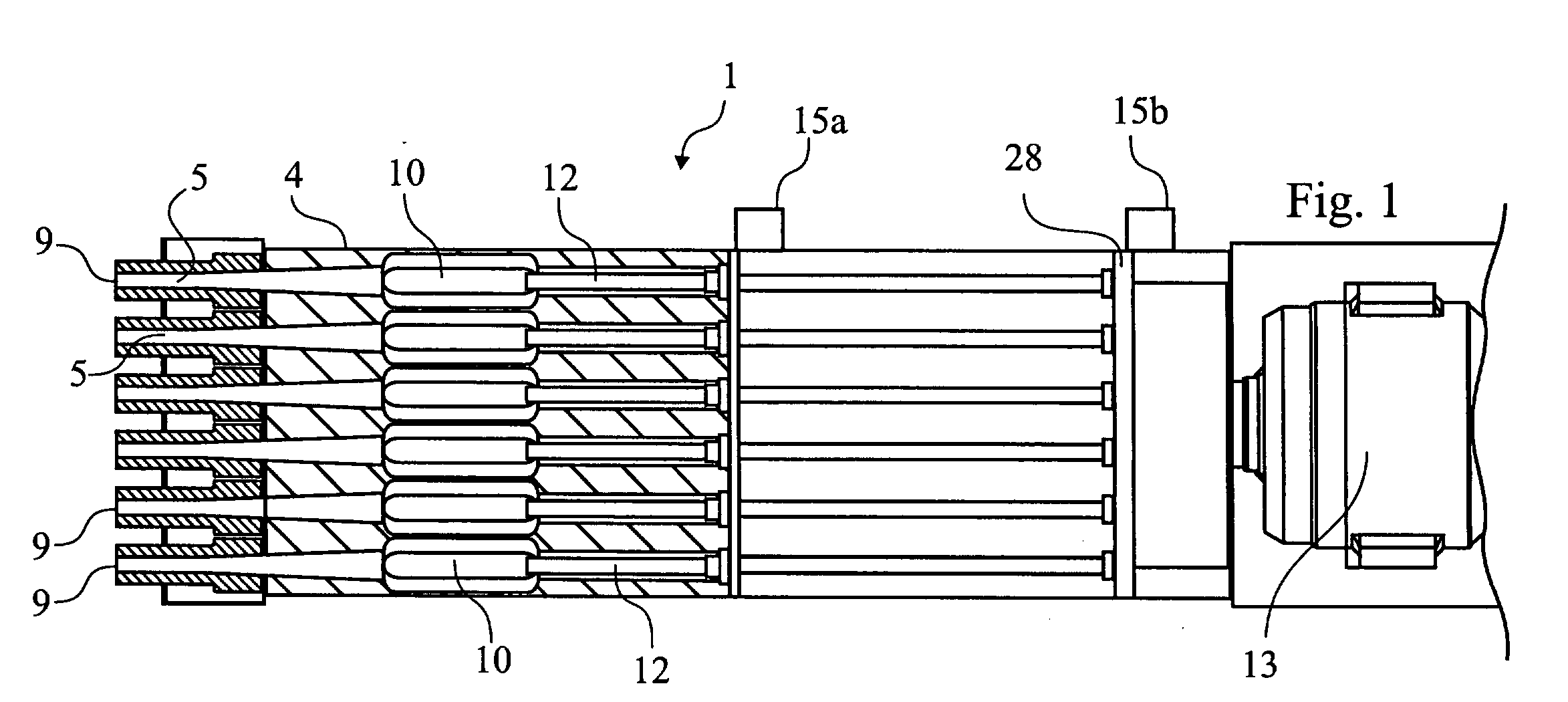
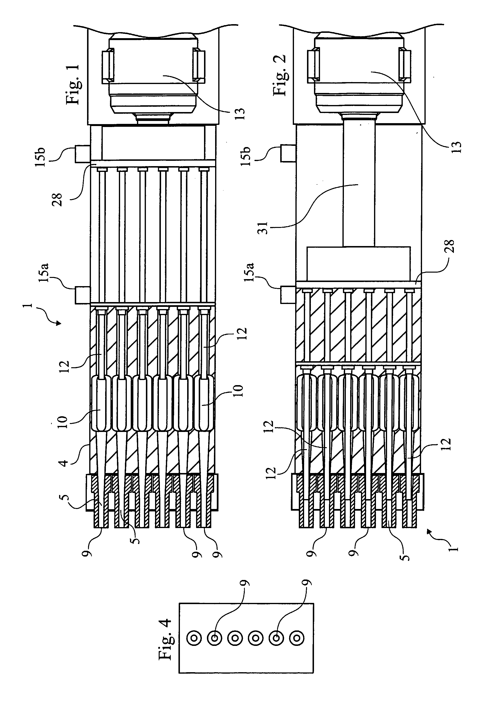
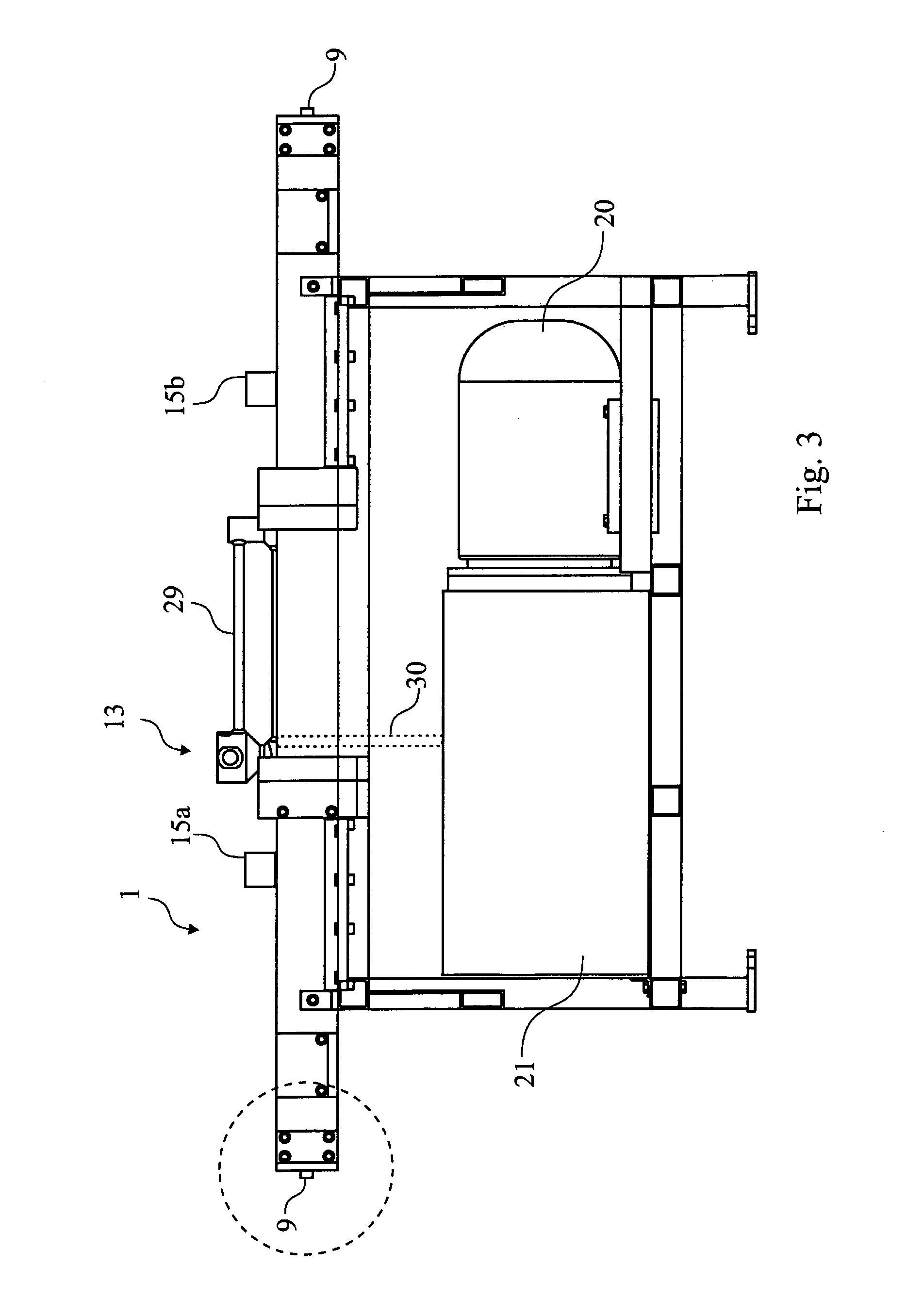
[0034]With reference to FIGS. 1-6, a machine 1 for making fuel pellets 2 is shown. As is shown in FIG. 5, combustible material 3 is fed to a hopper 10 in a machine 1 for making fuel pellets. The combustible material 3 may be e.g. saw dust, comminuted straw, bark, needles or leaves or similar. The material may also contain waste from grain processing. FIG. 5 indicates that the combustible material can be led to the hopper 10, via a funnel 11. The hopper 10 is shown in FIG. 5 to be positioned in a female part 4 (i.e. a female tool 4) having at least one elongated through passage 5 comprising at least one converging section 6. In preferred embodiments, the converging section 6 can have a conicity of about 1:10. The female part / tool 4 can be a tube / pipe 4 with one through passage, but can also be a continuous block with a plurality of through passages 5. The machine also comprises a male part 12 in the form of a piston 12 arranged to conduct operating strokes in the elongated passage 5....


PUM


Abstract

The invention relates to a method and a machine for converting comminuted material, such as saw dust, into fuel pellets. In the method of the invention, starting material is pressed by a piston through an elongated passage having a converging cross-section. The stroke length of the piston varies over time. The machine of the invention relates to a pellets press having a variable stroke length.

Description

TECHNICAL FIELD[0001]The present invention relates to a method and a machine for making fuel pellets, in which combustible material, such as saw dust or straw, is compressed by pressing of a piston through a passage having at least one converging section.BACKGROUND OF THE INVENTION[0002]Wood shavings, such as sawdust and chips, result as a surplus material in e.g. saw mills. Such material can be used as a fuel. Chips and shavings however have a tendency to sinter in an incinerator. It is therefore necessary to convert the raw material into biopellets that should have a hard and smooth surface and that will flow freely when fed into an incinerator. Fuel pellets can also be made from other materials than saw dust. For example, fuel pellets can be made of straw. In order to convert the raw material into pellets, the material should be exposed to high pressure and high heat. It is known that when lignin-containing wood material is compressed at high pressure, lignin will be released and...

Claims


Application Information

Patent Timeline
Patent Type & Authority Applications(United States)
IPC IPC(8): B30B11/22B30BB30B11/26
CPCB30B11/26
Inventor DAVIDSSON, KENNETH
Owner MINIPELL
Learn More