

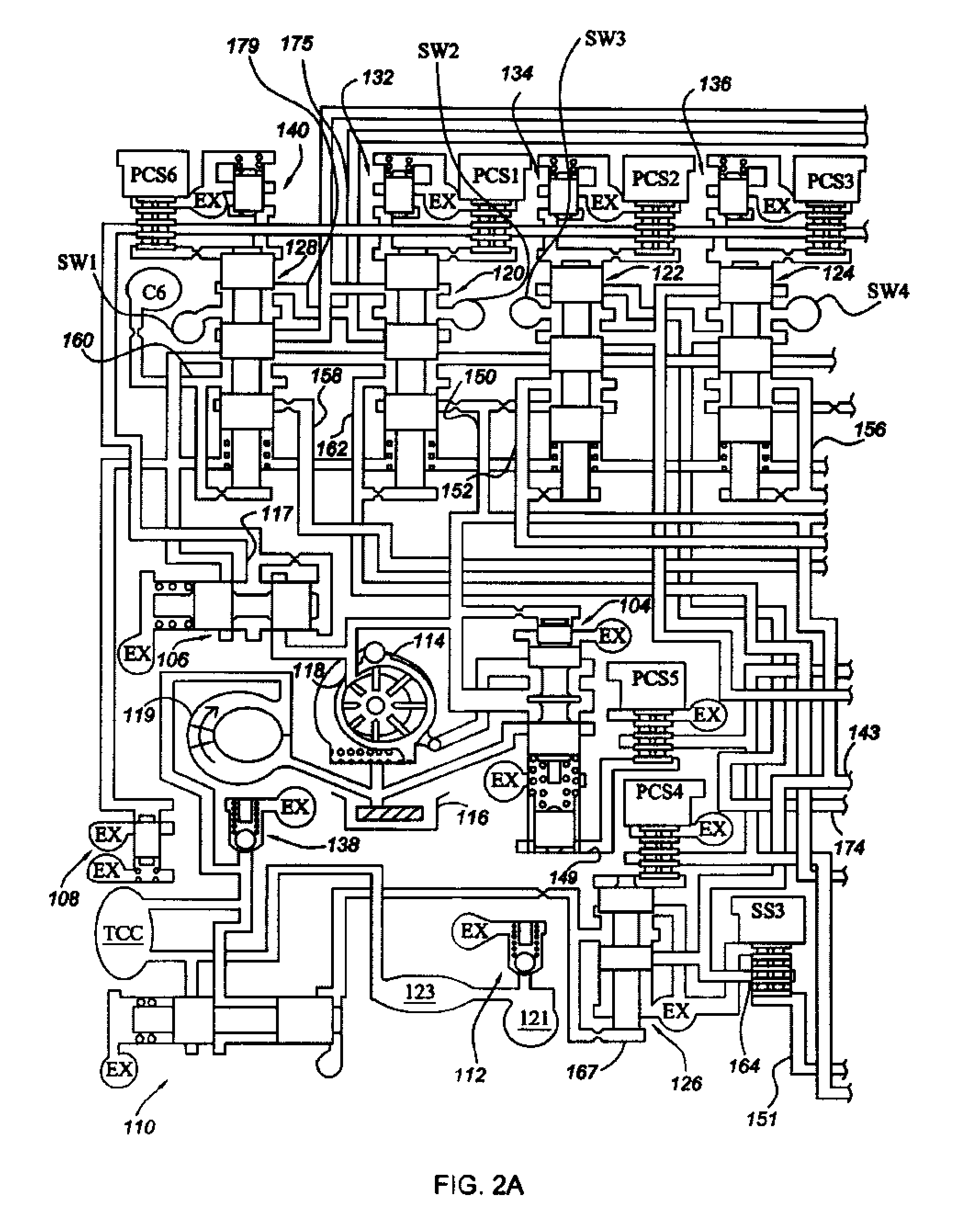
Electro-hydraulic control system with three-position dog clutch actuator valve
- Summary
- Abstract
- Description
- Claims
- Application Information
AI Technical Summary
Benefits of technology
Problems solved by technology
Method used
Image

Examples
Embodiment Construction
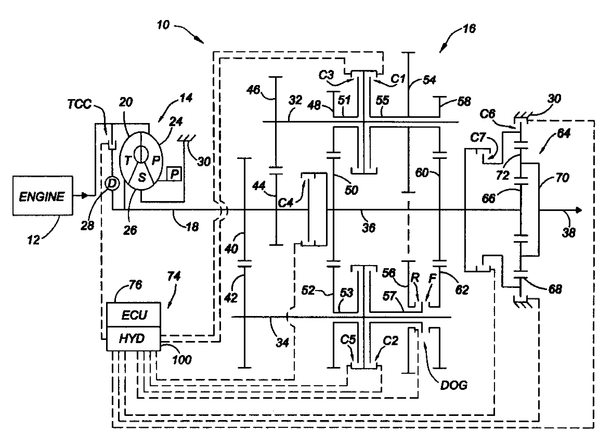
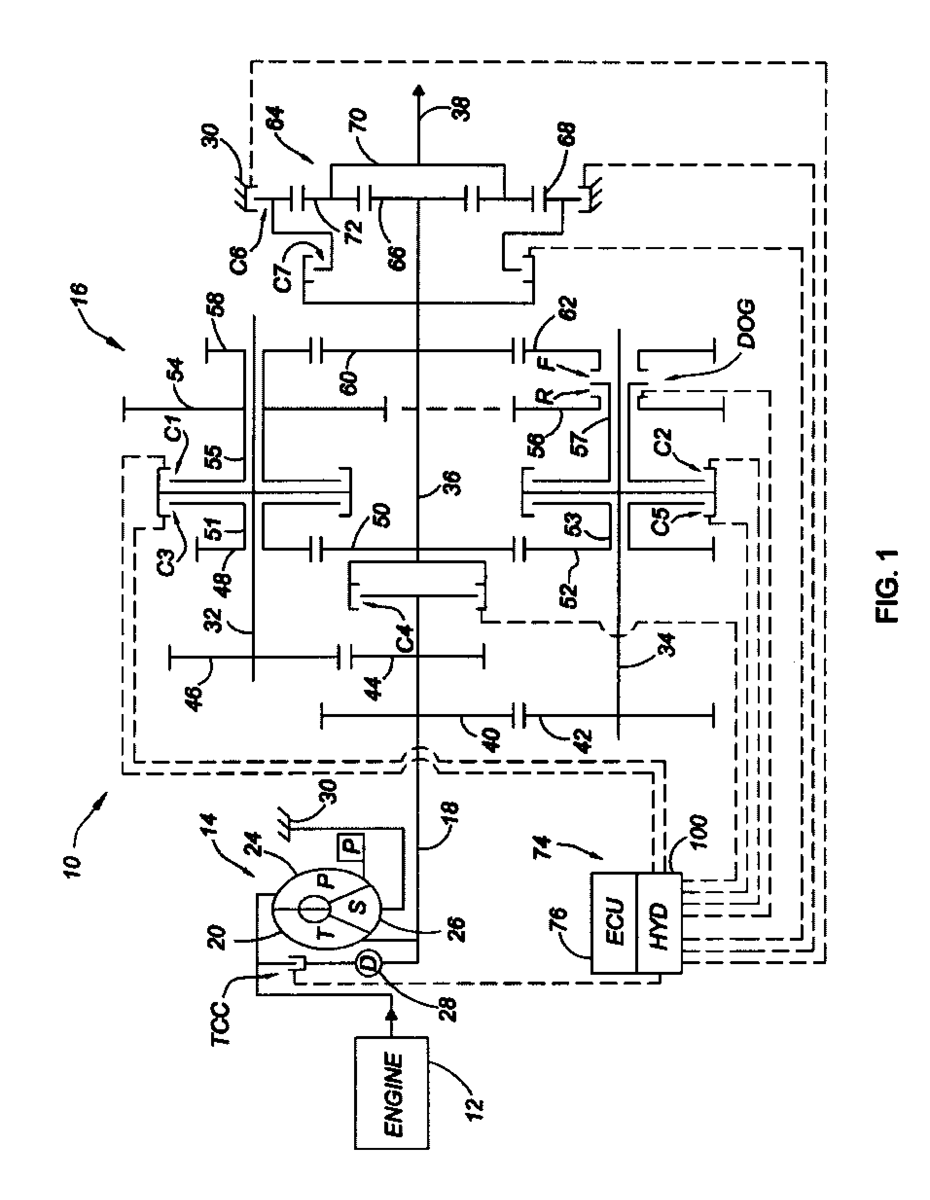
[0022]Referring to the drawings, wherein like reference numbers represent the same or corresponding parts throughout the several views, there is shown in FIG. 1 a powertrain 10. The powertrain 10 includes a power source or engine 12, a torque converter 14 and a countershaft transmission 16. The torque converter 14 is connected with the engine 12 and with a transmission input member 18 via a turbine 20. Selective engagement of a torque converter clutch TCC allows the engine 12 to be directly connected with the input shaft 18, bypassing the torque converter 14. The input member 18 is typically a shaft, and may be referred to as an input shaft herein. The torque converter 14 includes the turbine 20, a pump 24 and a stator 26. The converter stator 26 is grounded to a casing 30 through a typical one-way clutch that is not shown. A damper 28 is operatively connected to the engaged torque converter clutch TCC for absorbing vibration.
[0023]The transmission 16 includes a plurality of interme...
PUM
 Abstract
Description
Claims
Application Information