Sealed thermal interface component

Active Publication Date: 2008-08-14
LUNDELL MFG CORP
View PDF4 Cites 9 Cited by
  • Summary
  • Abstract
  • Description
  • Claims
  • Application Information

AI Technical Summary

Benefits of technology

[0009]In preferred embodiments, a sealed thermal interface component minimizes or eliminates the exudation of fluids, such as silicone oils, while preserving the excellent thermal conductivity of silicon-based thermal pad materials and enhancing the conformability of the component. In preferred embodiments, a foam frame surrounds a plurality of thermal pad portions formed of conformable thermal management material that may exude fluid under elevated temperatures or over time. Film encapsulates the foam-framed thermal pad portions, forming a sealed and partially evacuated thermal interface component. In a preferred embodiment of the invention, the thermal pads are formed of an elastomeric matrix material containing silicone, the foam frame is made of polyurethane, and the film is made of urethane.
[0010]In preferred embodiments, in the encapsulation process, air is evacuated from the interior of the encapsulation, thus eliminating of minimizing air gaps or pockets from within the sealed thermal interface component. The encapsulating film is heat sealed around the foam-framed thermal pad portions. The minimal amount of air present in the evacuated component is conducive to excellent thermal transfer characteristics.
[0011]Compression of thermal interface management materials between heat source and heat-sinking components generally causes some flowing of the conformable material. This increase in pressure causes the thermal pads to expand along axes perpendicular to the axis of compression. Such compression and the resultant flowage can rupture a simple encapsulation of the material due to the buildup of internal pressure caused by the flowage. The foam frame prevents rupture of the encapsulating film by compressing and allowing lateral expansion by the thermal pads within the component. The invention provides a thermal interface material flow management system.
[0012]Another feature and advantage of the preferred embodiments of the invention is the use of a heat-sealed encapsulating film. When heat-sealed, the encapsulating film prevents the exudation of silicone oils, maintains a vacuum within the sealed thermal interface component, enhancing thermal conductivity, and accommodates volumetric displacement of the foam-framed thermal pad without rupture or leakage during compression.
[0014]Another feature and advantage of the preferred embodiments of this invention is the creation of a vacuum within the encapsulating film while simultaneously heat sealing the encapsulating film. This removes and maintains the absence of air spaces from the sealed thermal interface. Air may inhibit heat transfer and the vacuum-induced lack of air within the thermal interface component increases the thermal transfer performance.

Problems solved by technology

Such compression and the resultant flowage can rupture a simple encapsulation of the material due to the buildup of internal pressure caused by the flowage.

Method used


Image

  • Sealed thermal interface component
  • Sealed thermal interface component
  • Sealed thermal interface component

Examples


Embodiment Construction

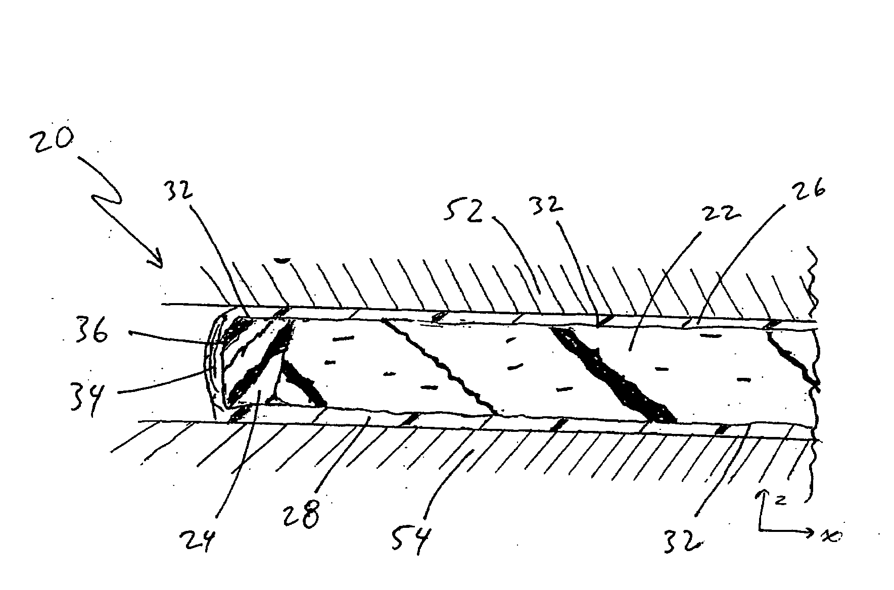
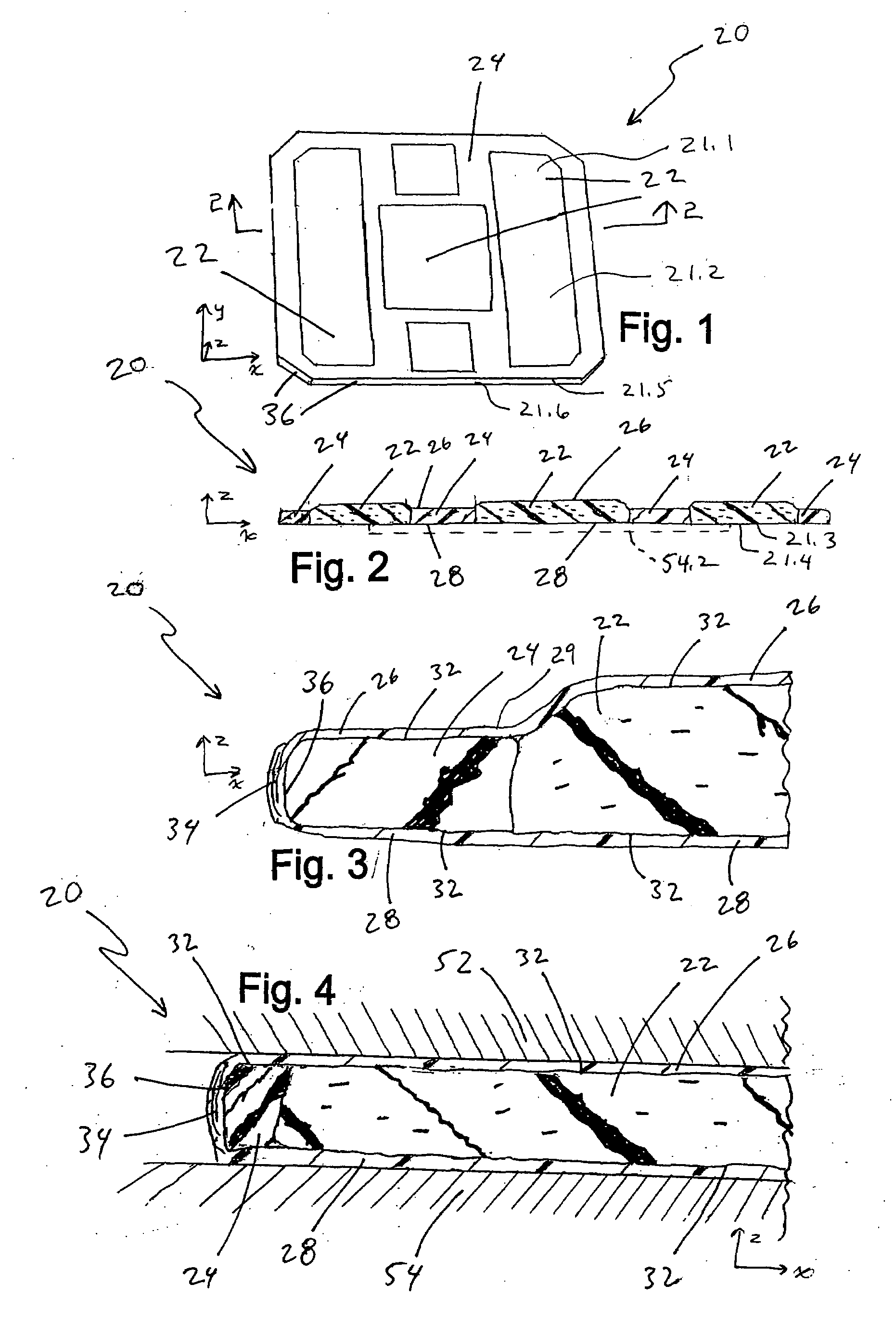
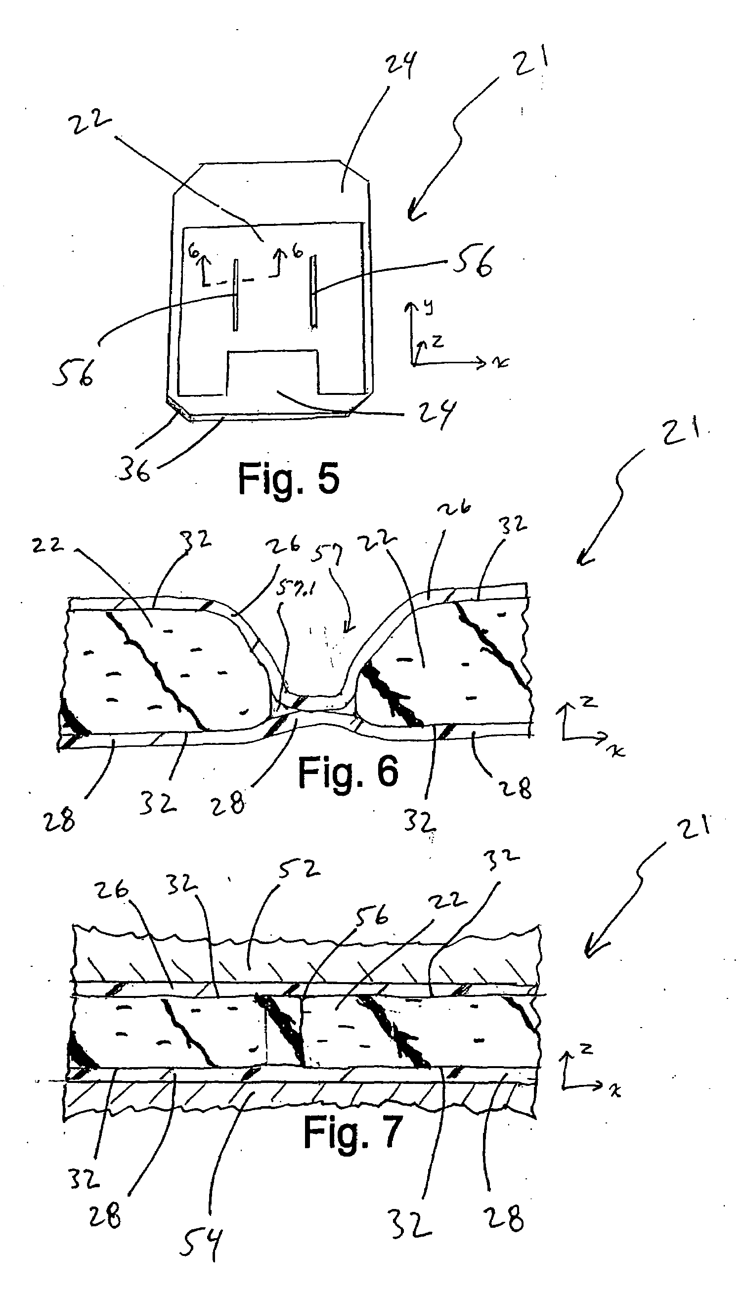
[0028]The present invention includes a heat-sealed thermal interface component for facilitating heat transfer between a heat source and a heat-sinking component. Referring to FIGS. 1, 2, 5, and 6 different embodiments of the sealed thermal interface component 20, 21 are illustrated. The components generally have a top side 21.1 with a top surface 21.2, a bottom side 21.3 with a bottom surface 21.4, and a side 21.5 with a side surface 21.6. In preferred embodiments the component is a sheet configuration with a maximum thickness of about 0.03 inches to about 0.50 inches (in the z direction of the x-y-z coordinate system) and surface area (in the x and y plane) of about 2 square inches to about 36 square inches. More preferably, the component has a thickness of 0.06 to 0.16 inches. The component may have a thickness that varies slightly due to different thicknesses of the base components and compression that occurs during manufacture, specifically the partial evacuation. When used here...


PUM

PropertyMeasurementUnit
Poweraaaaaaaaaa
Temperatureaaaaaaaaaa
Thicknessaaaaaaaaaa

Abstract

A sealed thermal interface component minimizes or eliminates the exudation of fluids, such as silicone oils, while preserving the excellent thermal conductivity of silicon-based thermal pad materials and enhancing the conformability of the component. In preferred embodiments, a foam frame surrounds a plurality of thermal pad portions formed of conformable thermal management material that may exude fluid under elevated temperatures or over time. Film encapsulates the foam-framed thermal pad portions, forming a sealed and partially evacuated thermal interface component. In one embodiment of the invention, the thermal pads are formed of an elastomeric matrix material containing silicone, the foam frame is made of urethane, and the film is made of polyurethane.

Description

BACKGROUND OF THE INVENTION[0001]This invention relates to thermal management materials that conduct heat from a heat source to a heat-sinking component and, more particularly, components that interface between a heat source and a heat switch.[0002]During operation, IC devices produce heat. Efficient cooling systems are sometimes necessary to prevent the failure of IC devices due to this heat. Certain types of cooling systems work by transferring heat from the surface of a heat source to a heat-sinking component that dissipates the heat. Heat sinking components typically are metal, for example aluminum, and have expanded surface areas to transfer heat to the environment or may have other mechanical cooling means. When the surface of a heat source, such as an integrated circuit or a module or package containing such components, is directly engaged with the surface of a heat-sinking component, surface irregularities may prevent optimum contact and result in air spaces located in the i...

Claims


Application Information

Patent Timeline
IPC IPC(8): H05K7/20
CPCH01L23/433H05K7/20454Y10T29/4935H01L2924/0002H01L2924/00
Inventor LUNDELL, TIMOTHY J.LUNDELL, THOMAS L.
Owner LUNDELL MFG CORP
Why Eureka
Try Eureka