Electric Nailing Mechanism

Inactive Publication Date: 2008-08-14
ACUMAN POWER TOOLS
View PDF10 Cites 40 Cited by
  • Summary
  • Abstract
  • Description
  • Claims
  • Application Information

AI Technical Summary

Benefits of technology

[0010]The primary objective of the present invention is to provide an electric nailing mechanism, wherein a striker is provided with one or two toothed bars that engage with a gear wheel assembly, a screw transmits power to the gear wheel assembly, and the gear wheel assembly is engaged with the toothed bars to drive the striker to move. It is noted that the gear wheel assembly includes a drive gear wheel and a travel gear, which are coaxially connected together. The drive gear wheel is round-shaped so as to engage with the sc

Problems solved by technology

Moreover, the use of the reduction mechanism 18 increases the mechanical loss of the motor 19, which results in a reduction of

Method used


Image

  • Electric Nailing Mechanism
  • Electric Nailing Mechanism
  • Electric Nailing Mechanism

Examples


Embodiment Construction

[0018]The present invention will be more clear from the following description when viewed together with the accompanying drawings, which show, for purpose of illustrations only, the preferred embodiment in accordance with the present invention.

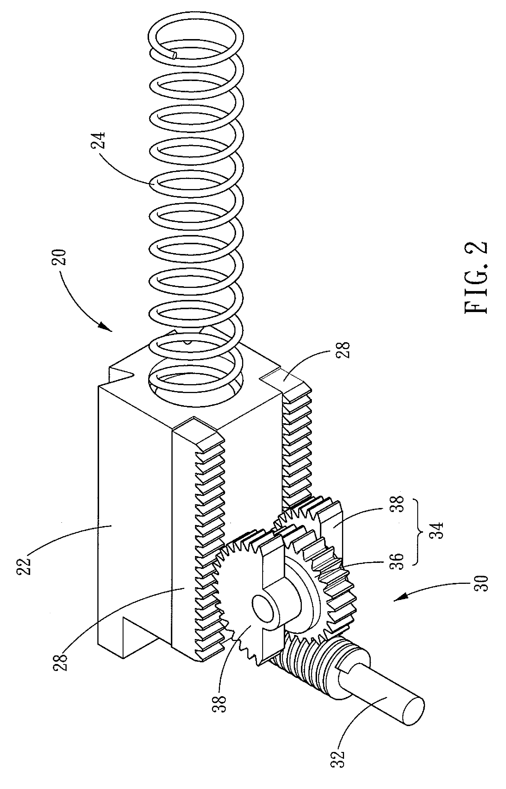
[0019]Referring to FIG. 2, a nailing mechanism 20 in accordance with the present invention is assembled in an electric tool (not shown) and is driven by a motor.

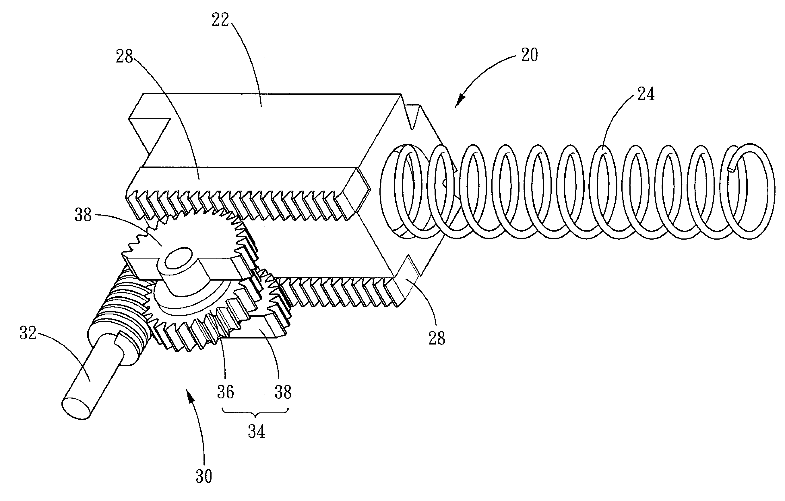
[0020]Referring to FIGS. 2 and 3, the electric nailing mechanism 20 comprises a striker 22 and an elastic member 24 with one end fixed at one end of the striker 22. The other end of the elastic member 24 is fixed to a stationary end 26. On a surface of the striker 11 is disposed one or two toothed bars 28, and there are two toothed bars 28 in the FIG. 2.

[0021]A driving assembly 30 is disposed on a surface of the striker 11 and engages with the toothed bars 28. The driving assembly 30 comprises a screw 32 and a gear wheel assembly 34. The screw 32 is driven to rotate continuously by mot...


PUM


Abstract

An electric nailing mechanism comprises a striker, an elastic member, one or two toothed bars, and a driving assembly. One end of the elastic member is fixed at one end of the striker. The toothed bars are disposed on a surface of the striker. The driving assembly comprises a screw, a drive gear wheel and one or two travel gears. The drive gear wheel is engaged with the screw and the drive gear wheel and the travel gears are coaxially connected together, so that the drive gear wheel and the travel gears can be rotated synchronously in the same direction. The travel gears are fan-shaped and are engaged with the toothed bars. By such arrangements, the driving assembly takes up a smaller space and the manufacture for the mechanism is much easier.

Description

BACKGROUND OF THE INVENTION[0001]1. Field of the Invention[0002]The present invention relates to an electric nailing mechanism, and more particularly to an electric nailing mechanism that is assembled in an electric tool and can automatically and repeatedly strike nails.[0003]2. Description of the Prior Art[0004]A conventional nailing mechanism for an electric tool performs striking action through a powerful striker that can move to and fro. Referring to FIG. 1, the conventional electric nailing mechanism comprises a striker 11, an elastic member 12, a first gear wheel 14, a second gear wheel 15, and a motor 19. One end of the elastic member 12 is fixed to the striker 11, and another end is fixed to a stationary end 13. The first gear wheel 14 is engaged with the second gear wheel 15, and two guide shafts 16 and 17 are disposed on the surface of the first gear wheel 14 and the second gear wheel 15 and are connected to the striker. When the output power of the motor 19 is transmitted...

Claims


Application Information

Patent Timeline
IPC IPC(8): B25C1/06
CPCB25C1/06
Inventor CHANG, CHIN-HSIUNGLIN, WEN-PINWANG, YAN-SHIANG
Owner ACUMAN POWER TOOLS
Why Eureka
Try Eureka