System for controlling flight direction

a flight direction and control system technology, applied in the field of fixed-wing aircrafts, can solve the problems of single-propeller aircrafts without additional airflow over the stabilizers and rudders, slow flying gliders or flapping wing aircraft like ornithopters, and lack of twin-engine airplanes. the effect of low cos

Active Publication Date: 2008-08-14
FLIR UNMANNED AERIAL SYST AS
View PDF20 Cites 24 Cited by
  • Summary
  • Abstract
  • Description
  • Claims
  • Application Information

AI Technical Summary

Benefits of technology

[0012]The present invention aims at fulfilling the need for a very simple and low cost way of controlling the flight direction of an aircraft flying slowly or with a high angle of attack by changing the incidence angles of its wings. Furthermore such control means could be used to control a slow flying flapping wing aircraft.
[0013]A control means that receives a control signal indicating a left turn increases the incidence angle and thereby also the angle of attack on the left wing and reduces it on the right wing. For a right turn the opposite action is performed. An aircraft that utilizes the current invention for directional control will benefit from having airfoils (e.g. flat plates) that experiences increased drag as the angle of attack increases but have a generally constant lift at high and increasing angles of attack.

Problems solved by technology

Twin-engine airplanes, very slow flying gliders or flapping wing aircrafts like ornithopters, however, lack the additional airflow over the stabilizers and rudder that single propeller aircrafts normally have.
For these kinds of aircrafts it can be more difficult to get a good directional control.
This solution is believed to be both fragile and complicated.
This tendency makes it more difficult to perform tight maneuvers with this system.
Especially for slowly flying aircraft with high angles of attack and for flapping wing aircrafts the existing systems have limitations.

Method used


Image

  • System for controlling flight direction
  • System for controlling flight direction
  • System for controlling flight direction

Examples


Embodiment Construction

[0026]In the following the present invention will be discussed and the preferred embodiment described by referring to the accompanying drawings. Alternative embodiments will also be discussed, however, people skilled in the art will realize other applications and modifications within the scope of the invention as defined in the enclosed independent claims.

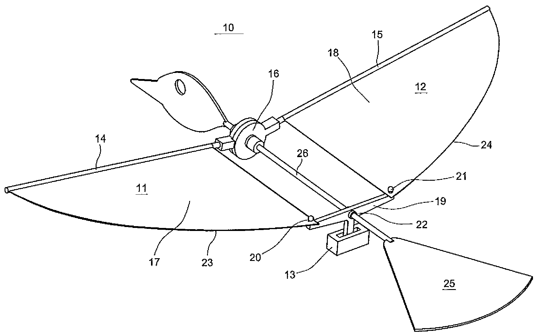
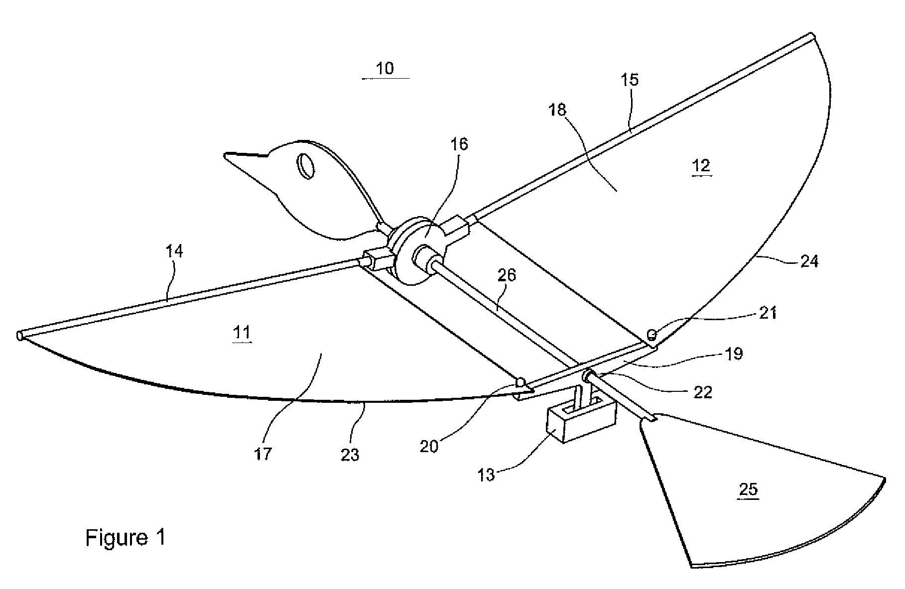
[0027]In FIG. 1 the preferred embodiment of an aircraft (10) according to the present invention is shown. It is a flapping wing aircraft, an ornithopter, utilizing a control means to control the flight direction. The present invention aims at fulfilling the need for a very simple, low cost and effective way of controlling the flight direction of an aircraft flying slowly or with a high angle of attack.

[0028]Normally an aircraft depends on changes in the lift on its wings to control the flight direction. Utilizing the current invention it is, however, possible to manoeuvre mainly based on drag differences between the left and right ...


PUM


Abstract

An aircraft that is enable to turn in a desired direction, and a method for controlling the flight direction of an aircraft, by employing differential drag on the respective wings. A control means that receives a control signal indicating a left turn increases the incidence angle on the left wing and reduces it on the right wing. For a right turn the opposite action is performed. The aircraft comprises airfoils that have increased drag as the incidence angle increases but have a generally constant lift.

Description

FIELD OF THE INVENTION [0001]The present invention relates to fixed wing aircrafts such as gliders and propeller driven airplanes and to flapping wing aircrafts such as ornithopters. In particular it relates to means and methods for controlling the flight direction of such aircrafts.BACKGROUND OF THE INVENTION [0002]Typically, ailerons and an elevator control the flight direction of airplanes. Ailerons are normally a part of the trailing edge, the aft part of the wing, which is hinged so it can tilt up and down. When the aileron is tilted down it alters the shape of the wing and in effect increases the incidence angle and the angle of attack and thereby also the lift on that wing. When the aileron is tilted down on one wing it is always tilted up on the opposite wing and thereby reducing the lift on this wing.[0003]The incidence angle is the angle between the cord line of the wing and the longitudinal axis of the aircraft itself. The angle of attack is on the other hand defined as t...

Claims


Application Information

Patent Timeline
Patent Type & Authority Applications(United States)
IPC IPC(8): B64C3/38A63H27/20
CPCA63H27/008A63H30/04A63H27/02
Inventor MUREN, PETTER
Owner FLIR UNMANNED AERIAL SYST AS
Why Eureka
Try Eureka