Failure Diagnosis Method of Seat Belt System and Seat Belt System Having Failure Diagnosis Function
a failure diagnosis and seat belt technology, applied in the direction of process and machine control, pedestrian/occupant safety arrangement, instruments, etc., can solve the problems of inability of seat belt apparatus to deliver the intended function, adversely affect the desired operation of the motor, vehicle occupants' abnormalities or discomfort, etc., to achieve easy failure diagnosis of the driving system
- Summary
- Abstract
- Description
- Claims
- Application Information
AI Technical Summary
Benefits of technology
Problems solved by technology
Method used
Image
Examples
first embodiment
[0062]FIG. 5 is a flow chart explaining the failure diagnosing routine of the first embodiment of the present invention.
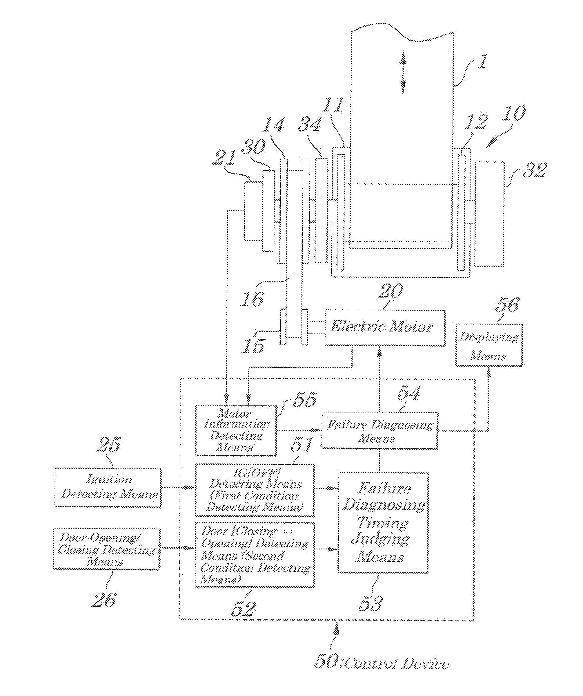
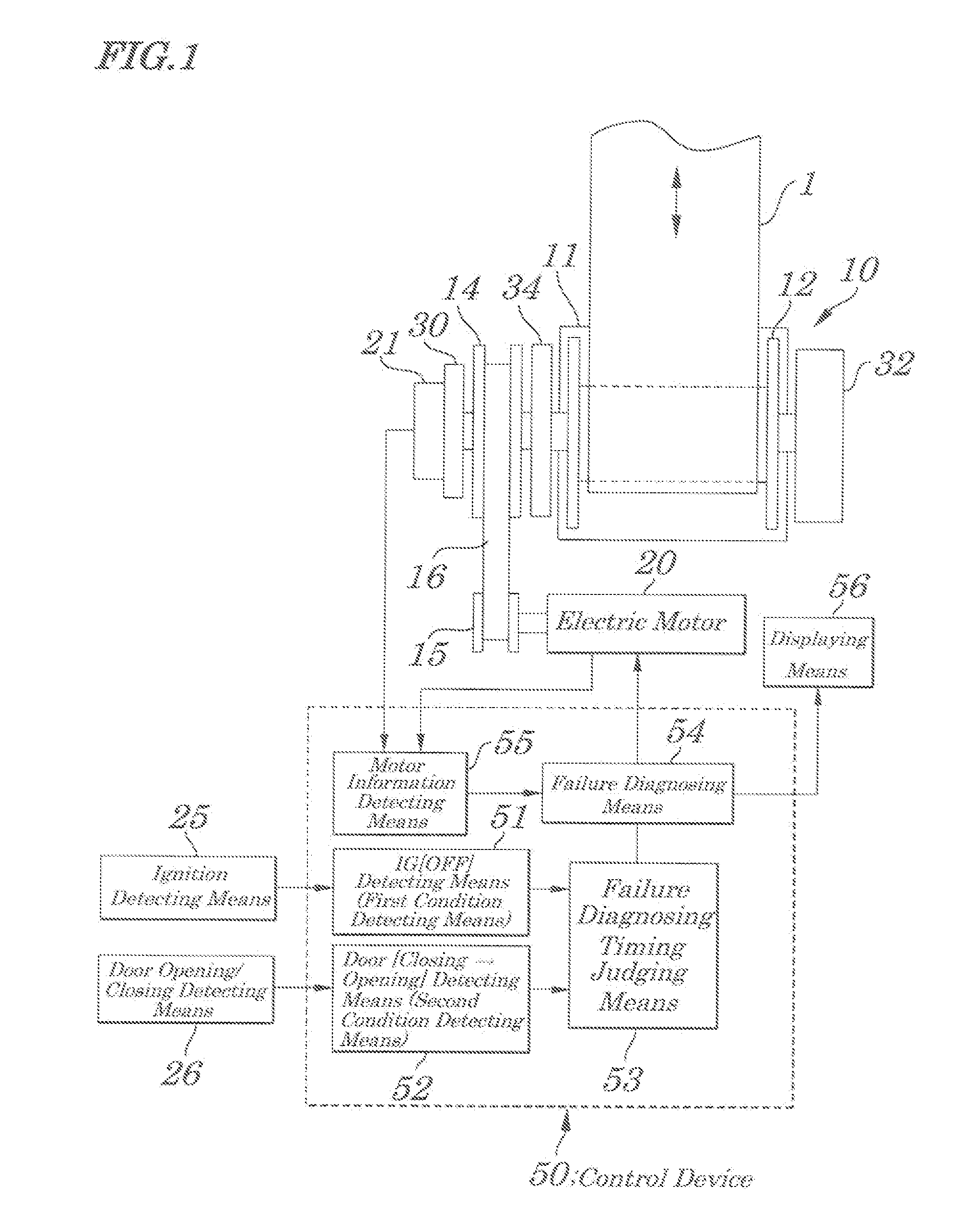
[0063]When this diagnosing routine is started, the failure FLAG is reset at initial Step S101 and, at next Step S102, a specified amount of driving currents is applied to the electric motor 20 (at a level that causes the electric motor 20 to be rotated reliably) and information about operations of the electric motor 20 in response to the application of the currents is read. Then, at Step S104, a judgment is made as to whether the driving system including the electric motor 20 is normal or abnormal and, when there is abnormality, at Step S105, based on the read information, the failure FLAG is set and the program returns back to its main routine.
second embodiment
[0064]FIG. 6 is a flow chart explaining a failure diagnosing routine of the second embodiment. In the embodiment, as a signal of the motor information detecting means 55, an amount of rotation R of the reel 12 (or the electric motor 20) is used.
[0065]When the failure diagnosing routine is started, at initial Step S201, a failure diagnosing FLAG is reset (to be 0) and at next Step S202, a specified amount of driving currents (at a level that causes the electric motor 20 to rotate reliably) is applied to the electric motor 201 so that the reel 12 rotates in a direction of drawing a seat belt. Then, at Step S203, the routine is on standby for a specified time “t1” and, thereafter, at Step S204, an amount of rotation R of the reel 21 is detected and, at Step S205, whether or not the amount of rotation R of the reel 21 is within an proper range is judged. That is, the judgment is made as to whether the amount of the rotation R is a preset specified amount A1 or more and a specified amoun...
third embodiment
[0068]FIG. 7 is a flow chart explaining a failure diagnosing routine of the third embodiment. In the embodiment, as a signal of the motor information detecting means 55, an amount of rotation R of the reel 12 (or the electric motor 20) is used.
[0069]When the failure diagnosing routine is started, at initial Step S301, the failure FLAG is reset (to be 0) and at next Step S302, a specified amount of driving currents (at a level that causes the electric motor 20 to rotate reliably) is applied to the electric motor 20 so that the reel 12 rotates in a direction of drawing (retracting) a seat belt. Then, at Step S303, the routine is on standby for a specified time “t1” and, thereafter, at Step S304, an amount of rotation R of the spool 21 is detected and, at Step S305, whether or not the amount of rotation R of the spool is within an proper range is judged. That is, the judgment is made as to whether the amount of the rotation R is a preset specified amount A1 or more and a specified amou...
PUM
 Abstract
Description
Claims
Application Information
 - R&D
- Intellectual Property
- Life Sciences
- Materials
- Tech Scout
- Unparalleled Data Quality
- Higher Quality Content
- 60% Fewer Hallucinations
Browse by: Latest US Patents, China's latest patents, Technical Efficacy Thesaurus, Application Domain, Technology Topic, Popular Technical Reports.
© 2025 PatSnap. All rights reserved.Legal|Privacy policy|Modern Slavery Act Transparency Statement|Sitemap|About US| Contact US: help@patsnap.com


