

Failure diagnosis apparatus for exhaust pressure sensor
a technology of failure diagnosis and exhaust pressure sensor, which is applied in the direction of fluid pressure measurement by mechanical elements, volume flow measurement devices, special data processing applications, etc., can solve the problems of erroneous determination and inability to detect a failure stuck
- Summary
- Abstract
- Description
- Claims
- Application Information
AI Technical Summary
Benefits of technology
Problems solved by technology
Method used
Image

Examples
first embodiment
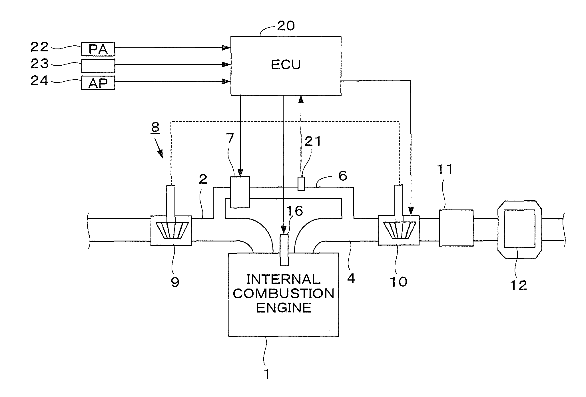
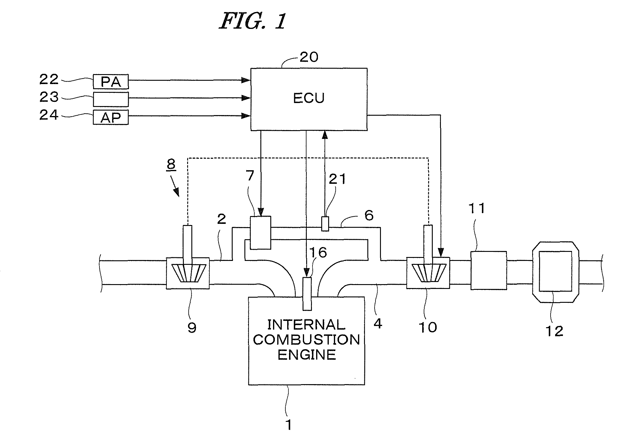
[0018]FIG. 1 is a schematic diagram showing the configuration of an internal combustion engine and a control system therefor according to an embodiment of the present invention. An internal combustion engine 1 (hereinafter referred to merely as “engine”) is a diesel engine in which fuel is injected directly into the cylinders, wherein each cylinder is provided with a fuel injection valve 16. The fuel injection valve 16 is electrically connected to an electronic control unit 20 (hereinafter referred to as “ECU”). The valve opening time period and valve opening timing of the fuel injection valve 16 are controlled by the ECU 20.
[0019]The engine 1 has an intake passage 2, an exhaust passage 4, an exhaust gas recirculation passage 6, and a turbocharger 8. The turbocharger 8 includes a turbine 10 and a compressor 9. The turbine 10 is driven by the kinetic energy of exhaust gases. The compressor 9, which is rotationally driven by the turbine 10, compresses the intake air. The turbine 10 ha...
second embodiment
[0042]In this embodiment, the first determination threshold value DPDTH1 and the second determination threshold value DPDTH2 in the first embodiment are set according to a valve opening command value LCMD of the EGR valve and the atmospheric pressure PA. The present embodiment is the same as the first embodiment except for the points described below.
[0043]FIG. 4 is a flowchart of the failure diagnosis process in this embodiment, and this process obtained by adding steps S14a, S14b, S14c, S22a, S22b, and S22c to the process shown in FIG. 3.
[0044]In step S14a, a KEGR table shown in FIG. 5A is retrieved according to the valve opening command value LCMD, to calculate an EGR correction coefficient KEGR. The KEGR table is set so that the EGR correction coefficient KEGR increases as the valve opening command value LCMD decreases. The KEGR table is set contemplating that the detected value of the exhaust pressure sensor 21 tends to increase as the valve opening command value LCMD decreases....
PUM
 Abstract
Description
Claims
Application Information