
Control apparatus for internal combustion engine

a control apparatus and internal combustion engine technology, applied in the direction of electric control, machines/engines, instruments, etc., can solve the problems of failure to supply, combustion and exhaust gas sometimes deteriorating, and the output of an oxygen sensor provided to an exhaust pipe is detected and the air-fuel ratio is improved. , to achieve the effect of improving the accuracy of failure diagnosis

Inactive Publication Date: 2011-01-06
MITSUBISHI ELECTRIC CORP
View PDF15 Cites 2 Cited by
  • Summary
  • Abstract
  • Description
  • Claims
  • Application Information

AI Technical Summary

Benefits of technology

This solution improves the accuracy of failure diagnosis by excluding temporary air-fuel ratio variations caused by alcohol concentration changes, thereby enhancing the reliability of steady air-fuel ratio control and preventing misdiagnosis of injector failures.

Problems solved by technology

For example, when a level of the amount of the fuel in a fuel tank is varied by a predetermined value or larger, an error in the air-fuel ratio based on an output from an oxygen sensor provided to an exhaust pipe is detected.
However, the air-fuel ratio in each individual cylinder is not necessarily the target air-fuel ratio due to a variation in injection characteristics of an injector for supplying a fuel to each of the cylinders, time degradation caused by clogging of a nozzle hole of the injector, or the like.
Thus, there is a variation in the air-fuel ratio between the cylinders, failing to supply an appropriate fuel injection amount to each of the cylinders in some cases.
As a result, the combustion and the exhaust gas sometimes deteriorate.
However, since the concentration starts changing from the inlet side of the delivery pipe because of a shape of the delivery pipe, the fuel at the same concentration cannot be supplied to all the injectors at the same timing Specifically, although the alcohol concentration starts changing at an early point in time in the cylinder close to the inlet of the delivery pipe, the alcohol concentration starts changing at the latest point in time in the cylinder on the remote side of the delivery pipe.
However, a difference in the change in the alcohol concentration in the injector between the cylinders cannot be detected.
Moreover, since a fluctuation in the oxygen sensor output becomes large due to the variation in the air-fuel ratio between the cylinders, the air-fuel ratio control (fuel injection amount control) cannot be accurately controlled by using the output value from the oxygen sensor, resulting in the deterioration of the combustion and the exhaust gas of each of the cylinders.
Therefore, as a result of the detection of the fluctuation in the oxygen sensor output value when the alcohol concentration changes, there is a fear that a wrong diagnosis of the occurrence of the failure may be made although the injector is normal.
Thus, there is a problem that the combustion and the exhaust gas are deteriorated.

Method used


Image

  • Control apparatus for internal combustion engine
  • Control apparatus for internal combustion engine
  • Control apparatus for internal combustion engine

Examples


first embodiment

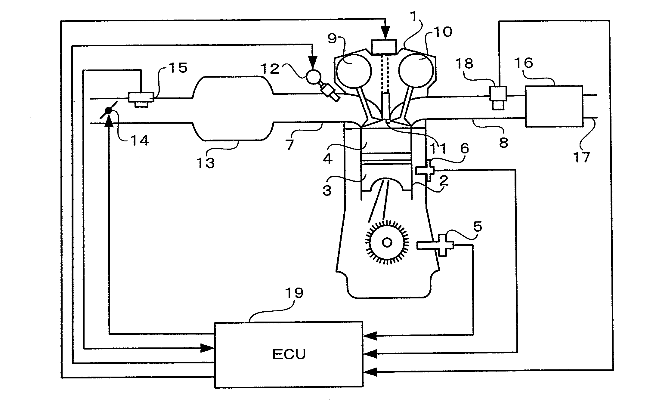
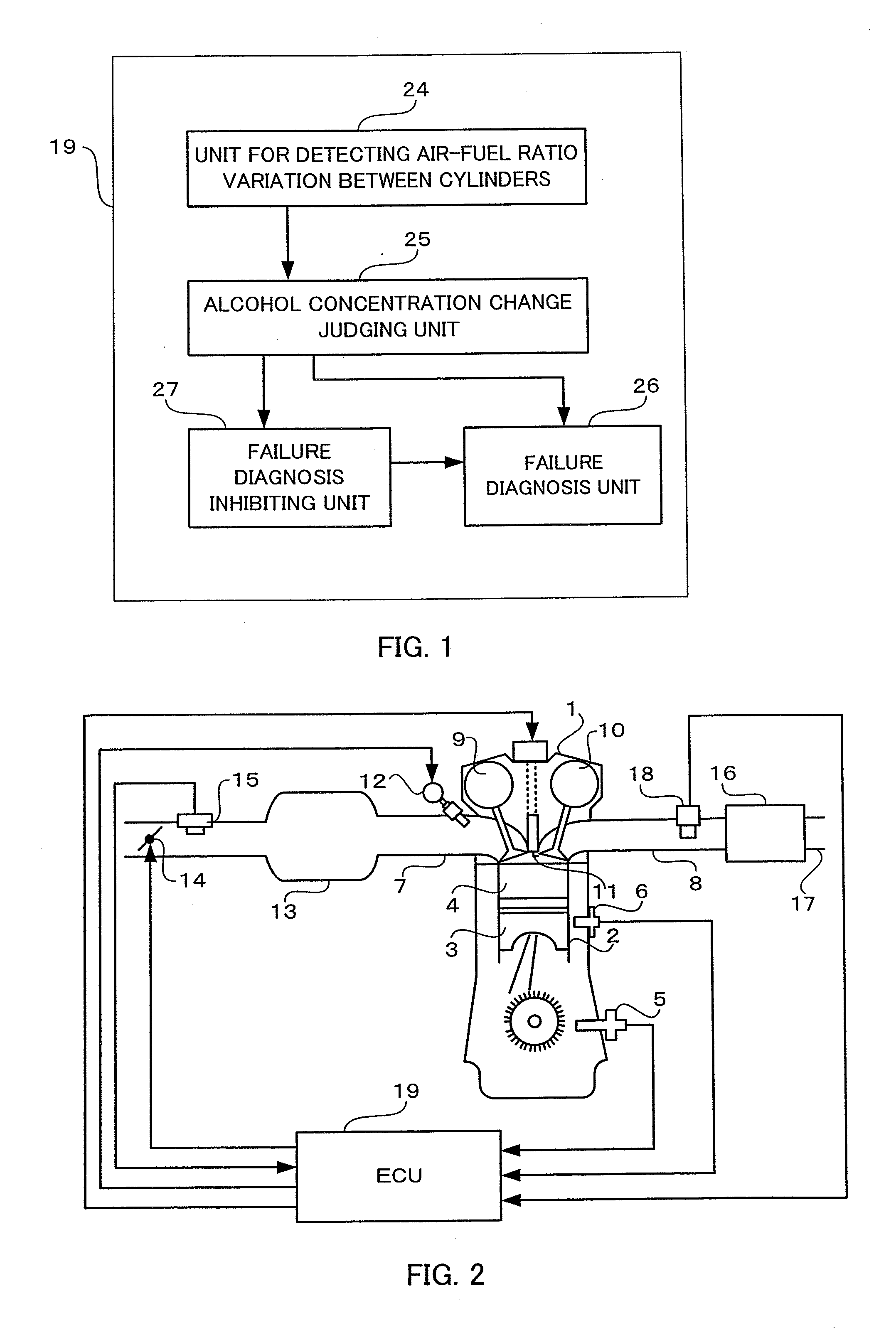
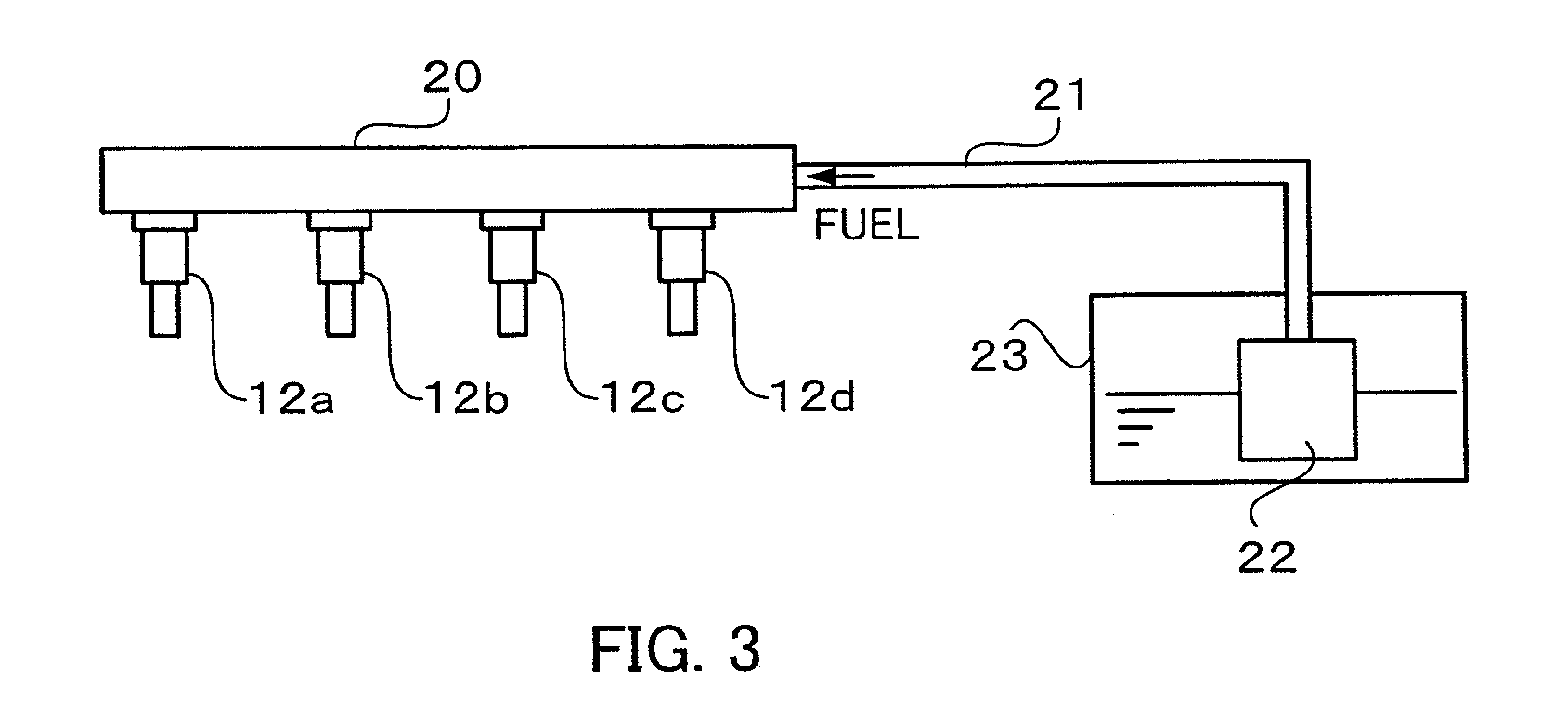
[0031]FIG. 1 is a block diagram illustrating functions of a control apparatus for an internal combustion engine according to a first embodiment of the present invention. FIG. 2 is a configuration diagram illustrating an entire system including the control apparatus for the internal combustion engine according to the first embodiment of the present invention. FIG. 3 is a configuration diagram illustrating a fuel flow path according to the first embodiment of the present invention. The internal combustion engine is generally provided with a plurality of cylinders. The internal combustion engine according to the first embodiment of the present invention is an in-line four cylinder internal combustion engine. In FIG. 2, one of the cylinders is illustrated.

[0032]An internal combustion engine (hereinafter, referred to as an “engine”) 1 according to the first embodiment of the present invention includes a cylinder 2 having a cylindrical shape and a piston 3 reciprocating in the cylinder 2....

second embodiment

[0064]FIG. 6 is a block diagram illustrating the functions of the control apparatus for the internal combustion engine according to a second embodiment of the present invention.

[0065]In the control apparatus for the internal combustion engine according to the second embodiment of the present invention, a fuel injection amount is corrected with a correction amount for each cylinder to absorb the air-fuel ratio variation between the cylinders occurring when the alcohol concentration changes. Since configuration diagrams illustrating the entire system including the control apparatus for the internal combustion engine and the fuel flow path according to the second embodiment of the present invention are the same as the configuration diagrams of FIGS. 2 and 3, the description thereof is herein omitted.

[0066]The program is stored in the ROM of an ECU 19B according to the second embodiment of the present invention. The CPU reads out the program stored in the ROM to execute the computation ...

third embodiment

[0093]In the control apparatus for the internal combustion engine according to a third embodiment of the present invention, the air-fuel ratio variation between the cylinders when the alcohol concentration changes is detected to execute the detection of the alcohol concentration.

[0094]FIG. 10 is a block diagram illustrating the functions of the control apparatus for the internal combustion engine according to the third embodiment of the present invention. Since configuration diagrams illustrating the entire system including the control apparatus for the internal combustion engine and the fuel flow path according to the third embodiment of the present invention are the same as the configuration diagrams of FIGS. 2 and 3, the description thereof is herein omitted.

[0095]The program is stored in the ROM of an ECU 19C according to the third embodiment of the present invention. The CPU reads out the program stored in the ROM to execute the computation according to the instruction of the p...


PUM


Abstract

The control apparatus for the internal combustion engine includes: a unit for detecting the change in the alcohol concentration of a fuel supplied to the internal combustion engine including a plurality of cylinders; a unit for detecting an air-fuel ratio variation between the plurality of cylinders; a unit for making the failure diagnosis when the air-fuel ratio variation between the plurality of cylinders exceeds a predetermined threshold value; and a unit for inhibiting the failure diagnosis executed based on the air-fuel ratio variation between the plurality of cylinders when the change in the alcohol concentration is detected.

Description

CROSS-REFERENCE TO RELATED APPLICATION[0001]This application is a divisional of U.S. application Ser. No. 12 / 357,855 filed Jan. 22, 2009, which is the disclosure of which is incorporated herein by reference in its entirety.BACKGROUND OF THE INVENTION[0002]1. Field of the Invention[0003]The present invention relates to a control apparatus that uses an alcohol fuel to be supplied to an internal combustion engine.[0004]2. Description of the Related Art[0005]Recently, with air pollution, changes in the oil situation, and the like, alcohol has attracted attention as an alternate fuel, which is to be supplied to an internal combustion engine (hereinafter, referred to as an “engine”). For example, a flexible fuel vehicle (FFV) using a blend fuel of alcohol and gasoline (at an alcohol concentration of 0% to 100%) has been put into practical use. However, since a theoretical air-fuel ratio (weight ratio of air and a fuel necessary for complete combustion of the fuel) of alcohol differs depen...

Claims


Application Information

Patent Timeline
Patent Type & Authority Applications(United States)
IPC IPC(8): F02M51/00
CPCF02D41/0025F02D41/0085F02D41/1443F02D41/1454Y02T10/36F02D2200/0611F02D19/0623F02D19/0655F02D19/084F02D41/1458Y02T10/30
Inventor MAEDA, OSAMUTAKUBO, HIDEKI
Owner MITSUBISHI ELECTRIC CORP
Learn More