Fluid Connector

a technology of connectors and connectors, applied in the direction of fluid pressure sealing joints, sleeves/socket joints, other medical devices, etc., can solve the problems of inability to easily remove the connection, complex assembly of parts, and inability to maintain fluid communication between tubing ends, etc., to achieve high separation resistance and low separation resistance

Active Publication Date: 2008-08-14
CUFFCO
View PDF22 Cites 66 Cited by
  • Summary
  • Abstract
  • Description
  • Claims
  • Application Information

AI Technical Summary

Benefits of technology

[0010]The present invention is a fluid connector for facilitating fluid communication between a first line and a second line that includes a male housing with a male proximal end portion adapted to be in fluid communication with the first line and a male distal end portion having an especially deformable ring. Wherein, a male longitudinal axis spans between the male housing proximal end portion and the male housing distal end portion. Also included in the fluid connector is a female housing including a female proximal end portion adapted to be in fluid communication with the second line and a female distal end portion with an elastically deformable annulus that removably engages the ring. Wherein, a female longitudinal axis spans between the female housing proximal end portion and the female housing distal end portion. Operationally the male housing and the female housing are ...

Problems solved by technology

There are many issues surrounding the fluid connector such as, how to handle the many different types of fluids and their properties, such as viscosity, miscibility of the various fluid components, also fluid pressure capability, fluid sealing capabilities at the connector interface, ease of assembly and disassembly, and fluid line interface particulars.
Bartholomew uses deflectable fingers that are received into a mating annular bead, wherein a locking tab that engages the annular channel to lock the connector, however, again resulting is a complex assembly of parts.
However, this aforementioned luer type engagement requires ancillary means for axial retention of the luer interface (interspaced between the tubing ends), wherein the luer interface itself has little axial retention other than the surface friction between the male and female frustroconical sections, unfortunately both the taper nature of the luer engagement and any pressure within the fluid line all act to forcibly separate the luer interface axially, resulting in an unacceptable situation for loss of fluid communication between the tubing ends.
Nordgren et al. uses an inwardly flexibly fingered collet that radially grips the outer tapered section of the male frustroconical section for a easily insertable interfac...

Method used


Image

  • Fluid Connector
  • Fluid Connector
  • Fluid Connector

Examples


Embodiment Construction

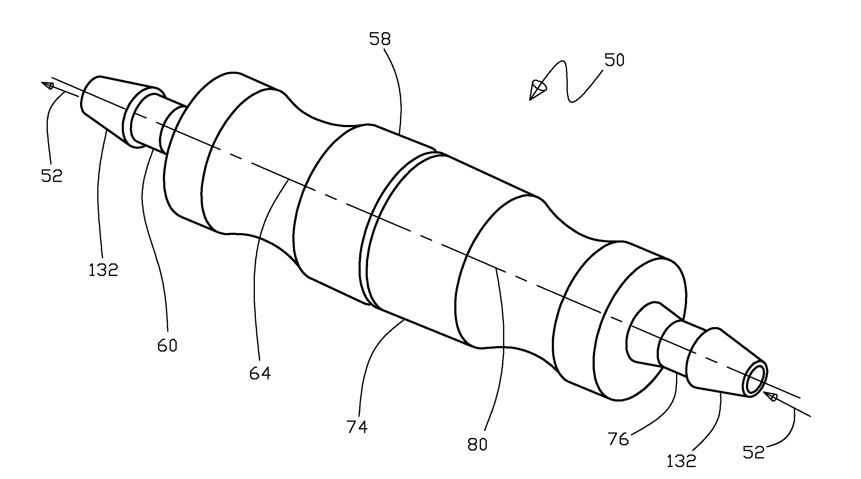
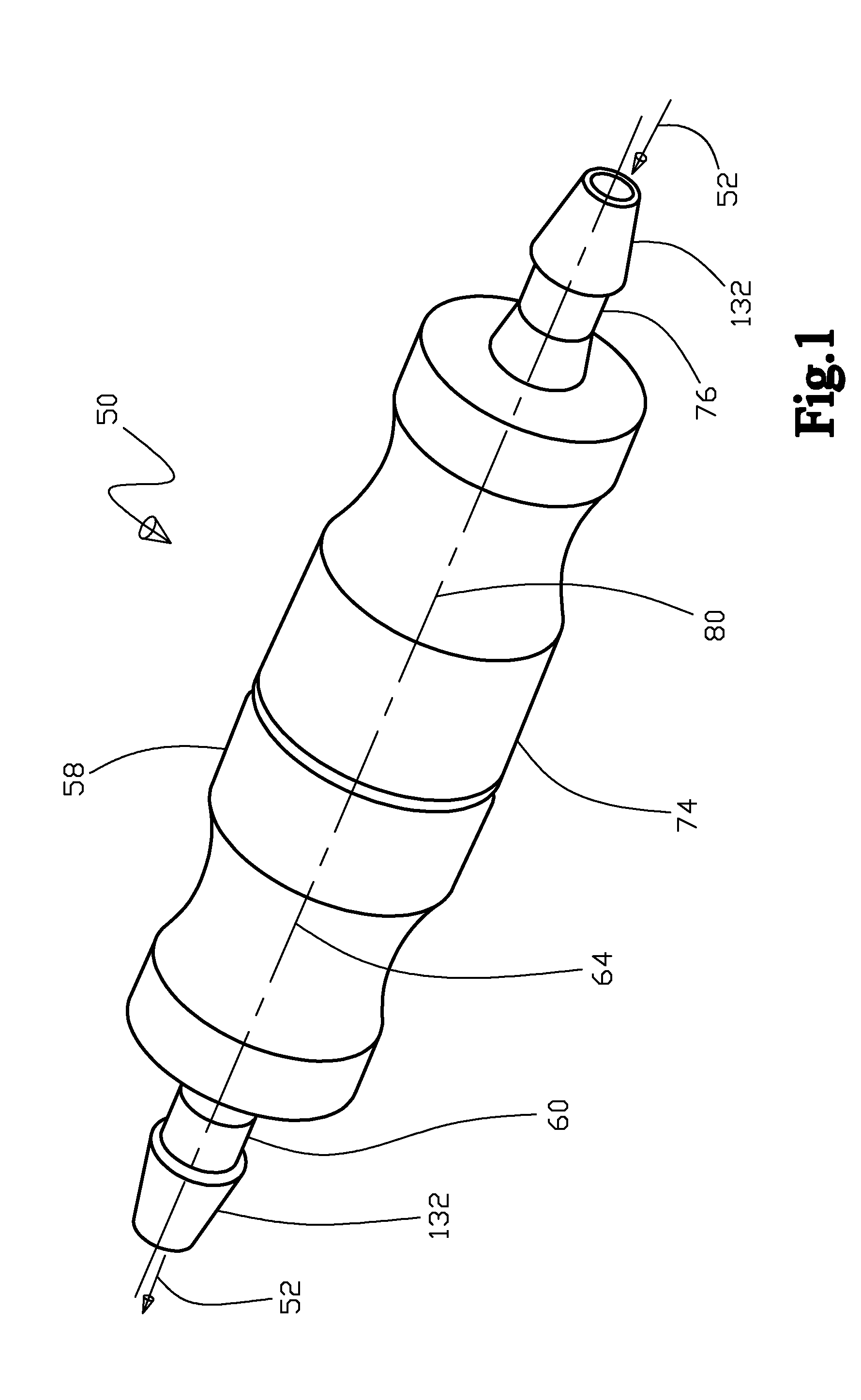
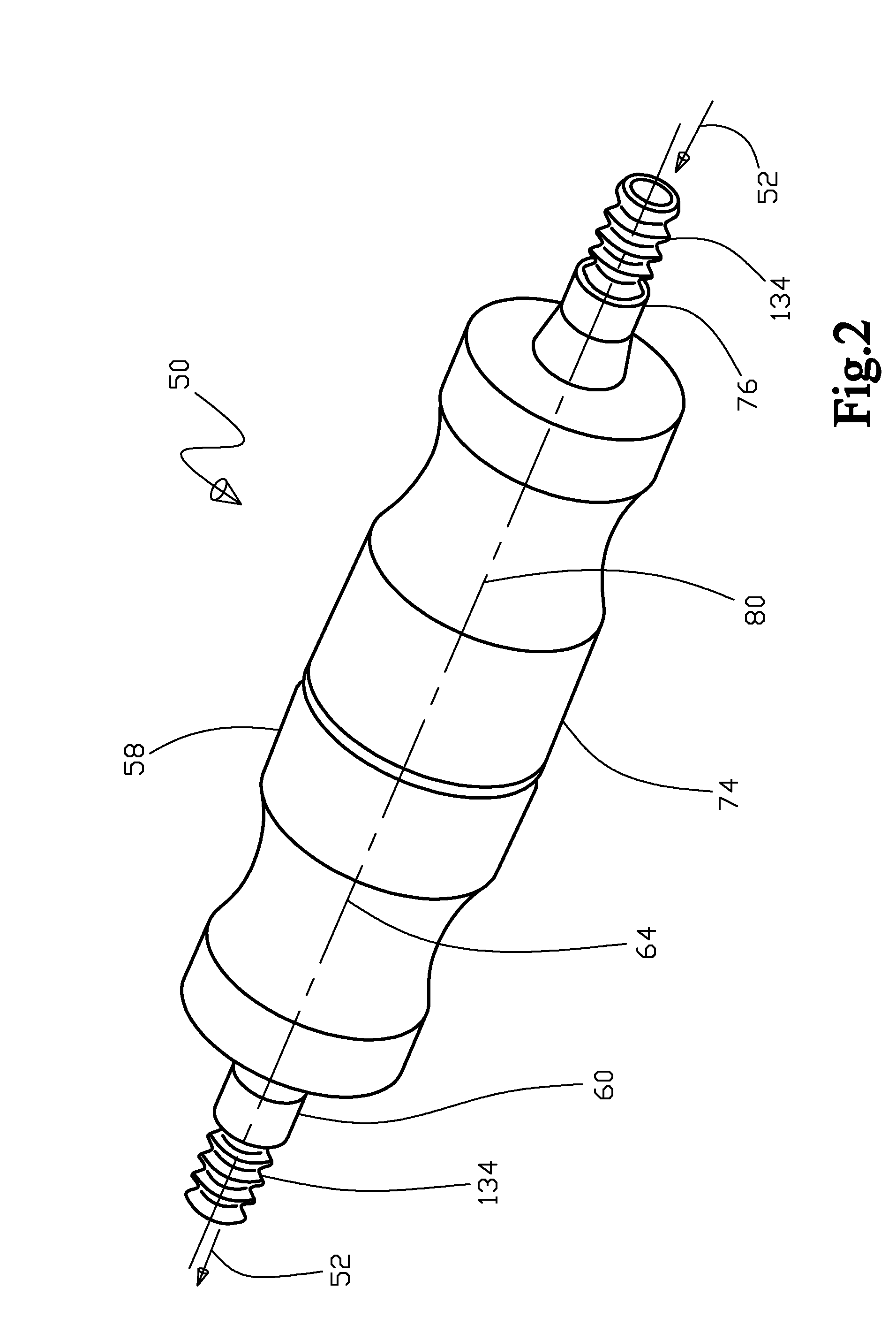
[0103]With initial reference to FIG. 1 shown is a perspective view of the fluid connector 50 with the male housing 58 and female housing 74 removably engaged 94 to one another, shown as being adapted for the barbed 132 first fluid line 54 and the second fluid line 56 interface. Continuing, FIG. 2 shows a perspective view of the fluid connector 50 with the male housing 58 and the female housing 74 removably engaged 94 to one another, shown as being adapted for the threaded 134 first fluid line 54 and the second fluid line 56 interface. Further, FIG. 3 shows a perspective view of the fluid connector 50 with the male housing 58 and female housing 74 removably engaged 94 to one another, shown as being adapted for the luer 136 first fluid line 54 and the second fluid line 56 interface. Next, FIG. 4 is a cross sectional view of the fluid connector 50 with the male housing 58 and female housing 74 removably engaged 94 with the face seal 140 in the form of an o-ring 142. Yet further, FIG. 5...


PUM


Abstract

A fluid connector and method of use is disclosed that includes a male housing with a male proximal end portion adapted to be in fluid communication with a first line and a male distal end portion having a resilient ring. Also included is a female housing with a female proximal end portion adapted to be in fluid communication with a second line and a female distal end portion with a resilient annulus that removably engages the ring. Operationally, the male and the female housings are configured at the annulus and ring engagement to have a high separating resistance axially and a low separating resistance transverse to the axial axis by manually applying a bending moment between the male and female engaged housings by a force transverse to the axial axis. Further included is structure for fluid sealing between the male and female housings when the annulus and ring are engaged.

Description

TECHNICAL FIELD[0001]The present invention generally relates to a fluid connector and more particularly to a removably engagable fluid connector that includes a sealing element for maintaining a substantially fluid tight connection for the purpose of facilitating fluid communication between a plurality of fluid lines.BACKGROUND OF INVENTION[0002]There are a variety of fluid connectors in the prior art. The majority of disclosed prior art fluid connectors are designed for quick (tool less) couple and release of a fluid line, usually by the use of latches or flexible fingers which involve additional moving parts and complication. There are many issues surrounding the fluid connector such as, how to handle the many different types of fluids and their properties, such as viscosity, miscibility of the various fluid components, also fluid pressure capability, fluid sealing capabilities at the connector interface, ease of assembly and disassembly, and fluid line interface particulars.[0003...

Claims


Application Information

Patent Timeline
IPC IPC(8): F16L17/06
CPCA61M16/0816A61M2202/0208F16L17/06A61M16/0672F16L21/035F16L37/02F16L21/03
Inventor KNIPPLE, LARRY EUGENESTONE, MARK ALLENSPLETT, DAVID WARREN
Owner CUFFCO
Why Eureka
Try Eureka