
Compensation Arrangement and Method For Operation Thereof

a compensation signal and input signal technology, applied in the field of compensation signal for cyclical input signal, can solve the problems of inability to reliably detect the first event, temperature will not be uniform throughout the sensor, and the best moment for compensation signal adjustment, etc., to achieve the effect of improving compensation

Active Publication Date: 2008-08-14
SENSATA TECH HOLLAND
View PDF17 Cites 11 Cited by
  • Summary
  • Abstract
  • Description
  • Claims
  • Application Information

AI Technical Summary

Benefits of technology

"The present invention provides an improved compensation method for cyclical input signals, particularly cylinder pressure signals, by detecting and adjusting the offset of the signal based on the temperature and other factors that may change during operation. The method uses a delay time period to perform the adjustment, which reduces errors in determining the crank angle and the offset compensation signal. The compensation signal is generated based on the detection of the first event and a second event in the cyclical output signal, and can be adjusted based on the output signal and a further input signal. The technical effect of the invention is to provide a more accurate and reliable compensation method for cyclical input signals, particularly for pressure glow plugs in engines."

Problems solved by technology

Furthermore, the temperature will not be uniform throughout the sensor.
It has been found that the instant of a reliable detection of the first event is not the best moment to perform the adjustment of the compensation signal.

Method used


Image

  • Compensation Arrangement and Method For Operation Thereof
  • Compensation Arrangement and Method For Operation Thereof
  • Compensation Arrangement and Method For Operation Thereof

Examples


Embodiment Construction

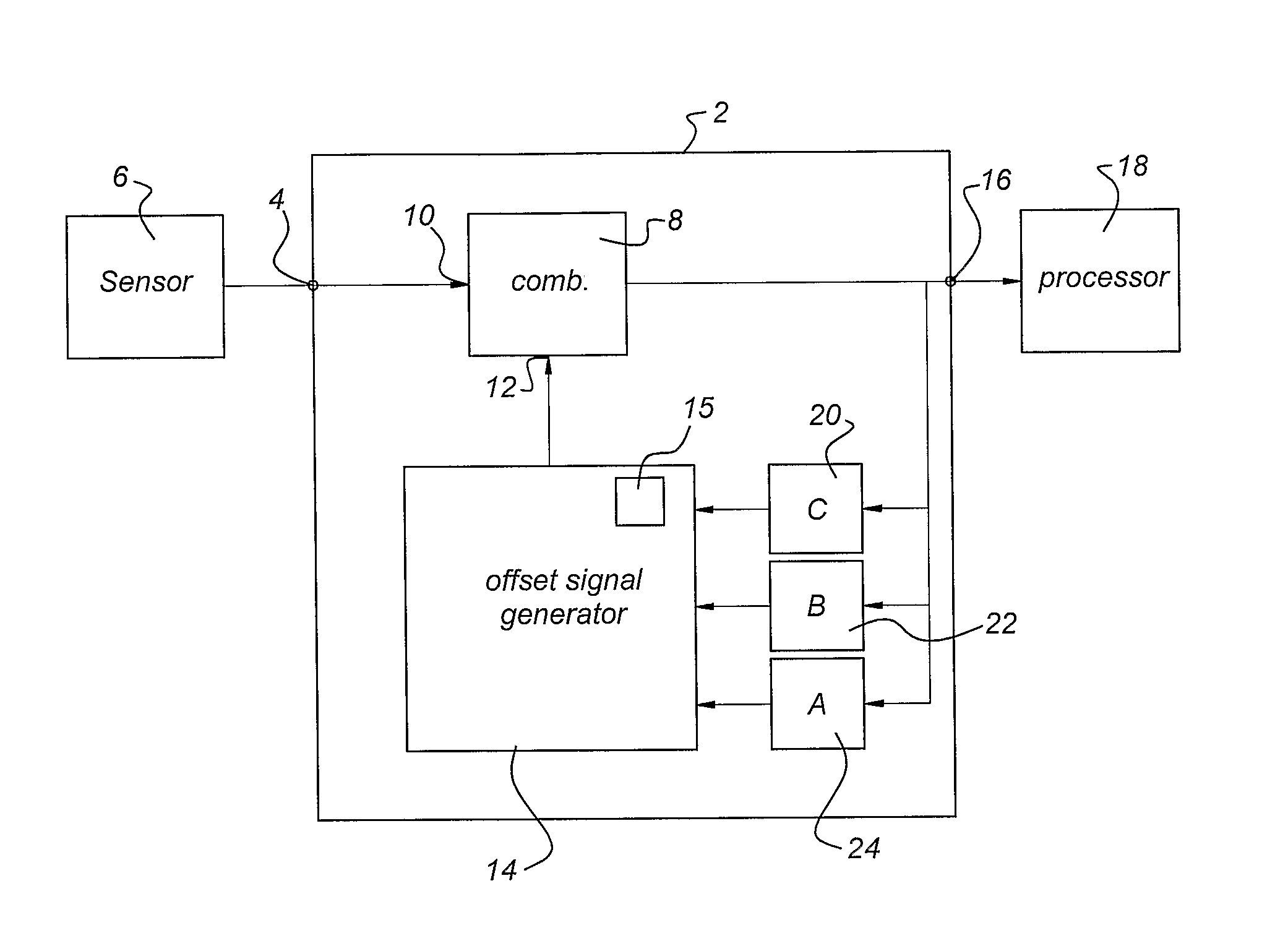
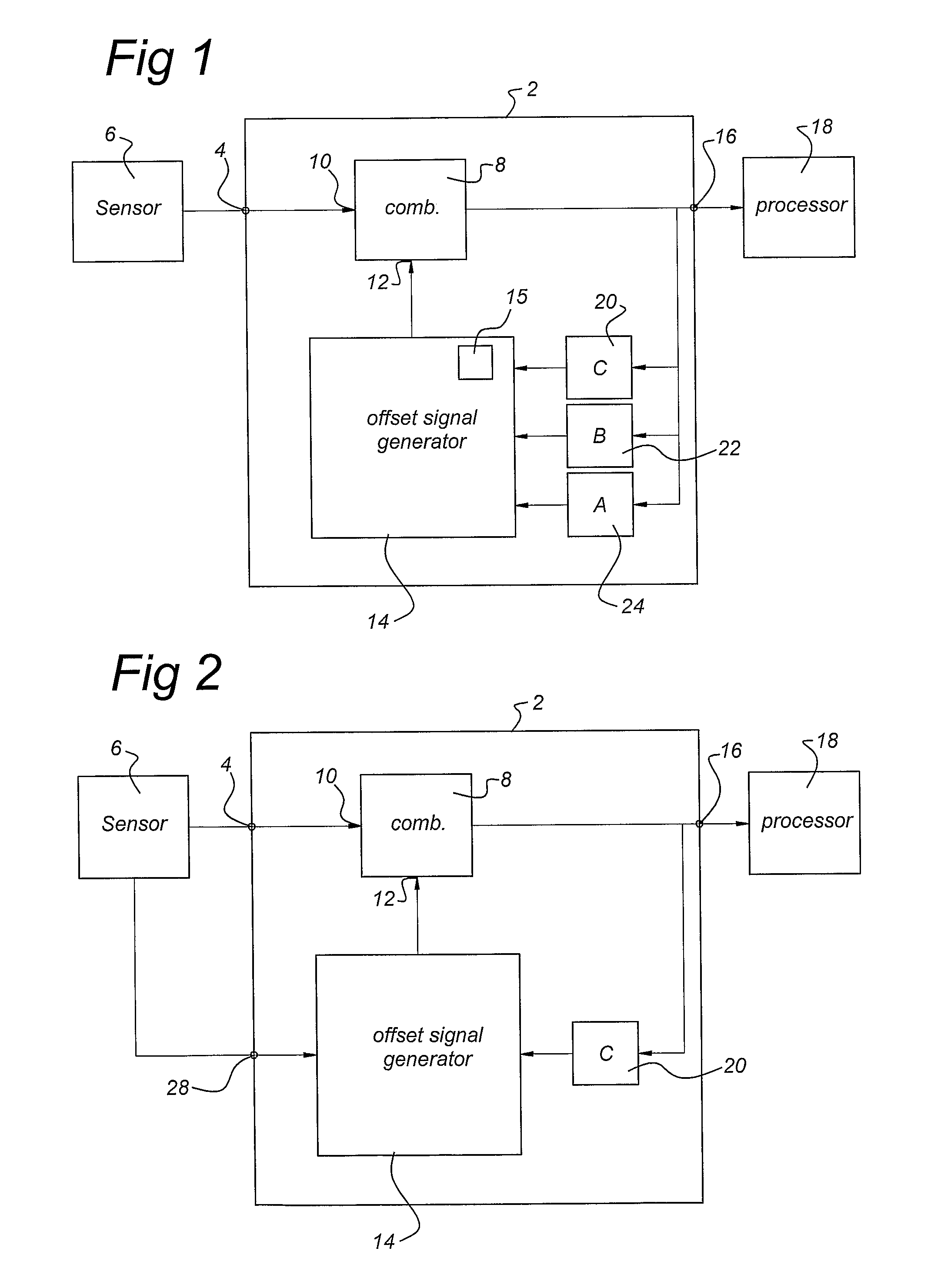
[0029]FIG. 1 shows a simplified block diagram of a first embodiment of an arrangement 2 for compensation according to the present invention. This embodiment will be discussed for compensating the offset in a cyclical input signal. The arrangement 2 comprises an input 4 for receiving the cyclical input signal. The cyclical input signal could be obtained from a pressure sensor 6, for example for measuring the pressure in a cylinder of an engine. The arrangement further comprises a signal combination unit 8 having a first input 10 coupled to the input 4 off the arrangement and a second input 12 coupled to an output of an offset signal generator unit 14. The signal combination unit 8 is arranged for combining the offset signal and the cyclical input signal to obtain the cyclical output signal. The signal combination unit 8 is normally arranged to subtract the offset signal from the cyclical input signal. However, if the offset signal generator 14 generates an inverted offset signal, the...


PUM


Abstract

An arrangement and method for providing compensation to a cyclical input signal is disclosed. The arrangement comprises a first detection unit (20) for detecting a first event in a cyclical output signal; a compensation signal generation unit (14) for generating a compensation signal; and a signal combination unit (8) for combining the compensation signal and the cyclical input signal to obtain the cyclical output signal. The compensation signal generation unit (14) is arranged to adjust the compensation signal at an instant which has a determined relationship with the detection of the first event. By adjusting the compensation signal at the right instant in a cycle of the cyclical output signal, the adjustment will not influence the further processing of the cyclical output signal. The method can be used to compensate the offset and sensitivity characteristics of a sensor.

Description

FIELD OF THE INVENTION [0001]The present invention relates to a method of compensation for a cyclical input signal. In a further aspect, the invention relates to an arrangement for compensation of a cyclical input signal. The invention has particular application in engine control to compensate behavior changes of a sensor, such as offset and sensitivity, during operation of said sensor, due to for example ambient temperature changes.PRIOR ART[0002]Pressure sensors are commonly known. A pressure sensor has an offset voltage, which is the output voltage of a sensor when no pressure is applied. Furthermore, a pressure sensor has an offset voltage temperature characteristic. This characteristics defines the variation of the offset voltage with changes in ambient temperature of the sensor.[0003]The Homogeneous Charge Compression Ignition Engine, HCCI, has the potential to combine the best of the spark ignition and compression ignition engines. These engines need active combustion control...

Claims


Application Information

Patent Timeline
Patent Type & Authority Applications(United States)
IPC IPC(8): G08B23/00
CPCG01D3/032G01L19/02G01L19/04G01L9/045G01D3/028G01L27/005G01L23/22G01L27/00
Inventor TIEK, TIMGENNISSEN, PAULUS THOMAS JOHANNES
Owner SENSATA TECH HOLLAND
Learn More