
Method of adaptively adjusting the target detection sensitivity of a motor vehicle radar

a technology of motor vehicles and target detection sensitivity, which is applied in the direction of reradiation, measurement devices, instruments, etc., can solve the problems of increasing the effective level of clutter or noise detected by the sensor, and unnecessarily limiting the target detection sensitivity of the system, so as to increase enhance the target detection sensitivity

Active Publication Date: 2008-08-14
APTIV TECH LTD
View PDF17 Cites 11 Cited by
  • Summary
  • Abstract
  • Description
  • Claims
  • Application Information

AI Technical Summary

Benefits of technology

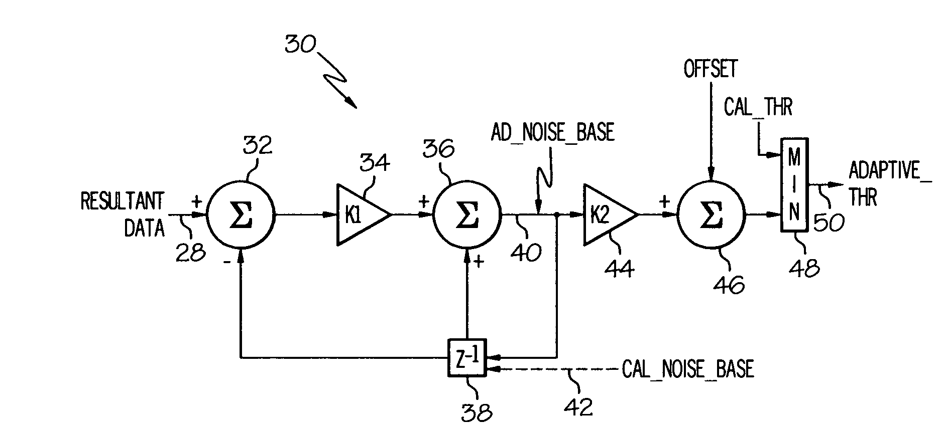
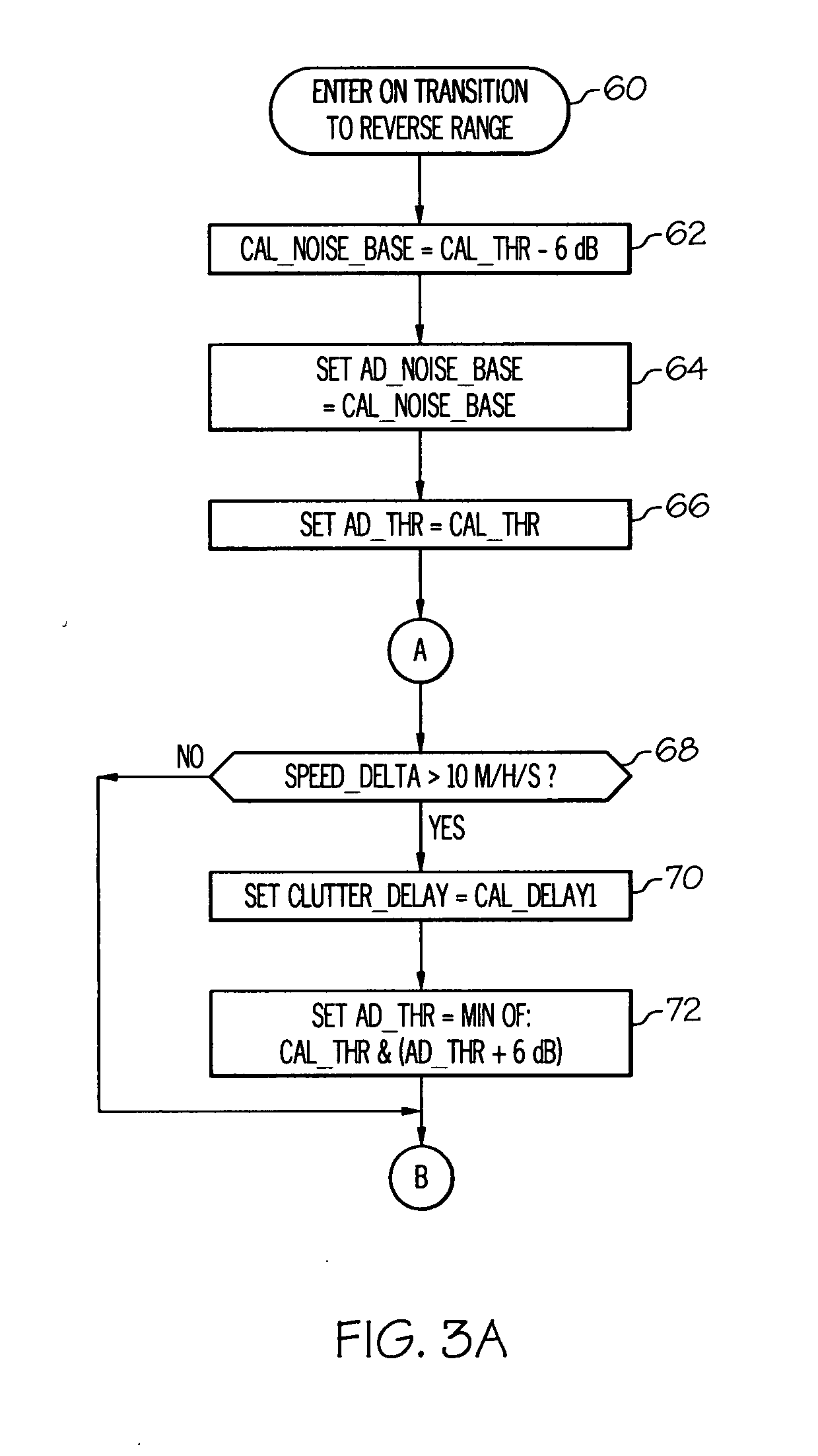
[0003]The present invention provides an improved method of operation for a radar-based motor vehicle BUA in which a calibrated target discrimination threshold is adaptively lowered under specified vehicle operating conditions to provide enhanced target detection sensitivity without causing false target detection. The threshold is initialized to a calibrated value on transition to the reverse range, and is thereafter subject to adaptive adjustment for increased target detection sensitivity so long as a target is not detected and a high-clutter condition is not in effect. The adaptive adjustment is carried out by low-pass filtering the resultant data of the radar sensor, starting with a factory-calibrated noise baseline, to determine the current noise level, and then calculating threshold from the determined noise level. The adaptive adjustment is suspended for a calibrated interval after target detection, and the threshold is increased when a high clutter condition is detected based on rate of change in vehicle speed.

Problems solved by technology

Although the bumper fascia protects the sensor module from physical damage and environmental contamination, it can also increase the effective level of clutter or noise detected by the sensor, particularly under conditions that cause the fascia to shift or flex.
Unfortunately, this can also unnecessarily limit the target detection sensitivity of the system because the same target discrimination threshold is used under all conditions.

Method used


Image

  • Method of adaptively adjusting the target detection sensitivity of a motor vehicle radar
  • Method of adaptively adjusting the target detection sensitivity of a motor vehicle radar
  • Method of adaptively adjusting the target detection sensitivity of a motor vehicle radar

Examples


Embodiment Construction

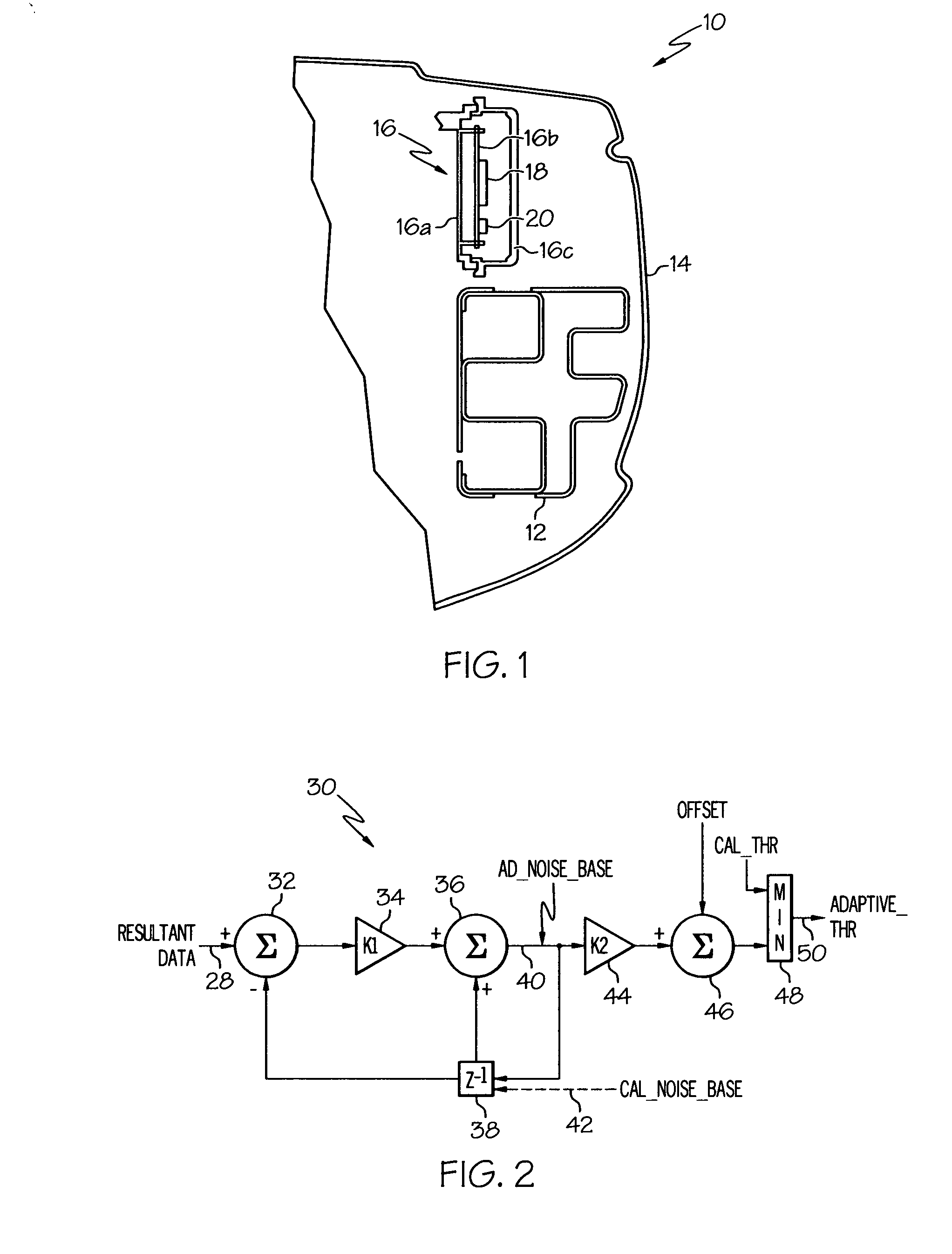
[0007]Referring to the drawings, and particularly to FIG. 1, the reference numeral 10 generally designates a motor vehicle, including a bumper frame 12, a molded plastic bumper fascia 14, and a radar-based BUA module 16. In the illustrated embodiment, a housing 16a of BUA module 16 is fastened to a vehicle frame element (not shown) above bumper frame 12. The electronic components of BUA 16, including a radar sensor 18 and a microprocessor-based signal processor 20, are mounted on a circuit board 16b, and a radome 16c fastened to the housing 16a encloses and environmentally seals the circuit board 16b and the electronic components 18 and 20. In use, the radar sensor 18 illuminates a defined area in the rear travel path of vehicle 10, and quantifies the reflected signal by range bin to form resultant data for comparison with a target discrimination threshold. A target is detected when the resultant data exceeds the threshold, and the presence or absence of targets over a prescribed pe...


PUM


Abstract

The factory-calibrated target discrimination threshold of a radar-based motor vehicle back-up aid is adaptively lowered under specified vehicle operating conditions to provide enhanced target detection sensitivity without causing false target detection. The threshold is initialized to the calibrated value on transition to the reverse range, and is thereafter subject to adaptive adjustment so long as a target is not detected and a high-clutter condition is not in effect. The adaptive adjustment is carried out by low-pass filtering the resultant data of the radar sensor, starting with a factory-calibrated noise baseline, to determine the current noise level, and then calculating the threshold from the noise level. The adaptive adjustment is suspended for an interval after target detection, and the threshold is increased when a high clutter condition is detected based on rate of change in vehicle speed.

Description

TECHNICAL FIELD[0001]The present invention relates to a radar-based back-up and parking aid for a motor vehicle, and more particularly to a method of adaptively setting a radar signal threshold for discriminating targets (i.e., objects of interest) from background clutter.BACKGROUND OF THE INVENTION[0002]Motor vehicles can be equipped with a radar-based back-up and parking aid (BUA) such as the Dual-Beam Radar Back-Up Aid produced by Delphi Corporation for producing audible and / or visual driver alerts when an obstacle is detected in the rear travel path of the vehicle. In a typical installation, the system includes a radar sensor module mounted in a protected location behind a plastic fascia that covers the rear bumper. Although the bumper fascia protects the sensor module from physical damage and environmental contamination, it can also increase the effective level of clutter or noise detected by the sensor, particularly under conditions that cause the fascia to shift or flex. Sinc...

Claims


Application Information

Patent Timeline
Patent Type & Authority Applications(United States)
IPC IPC(8): G01S13/08G01S13/931
CPCG01S7/2922G01S7/2927G01S2007/4082G01S13/931G01S2007/4091G01S7/4021G01S7/4082G01S7/4091
Inventor BANASZAK, THOMAS J.ILICIC, BORIS I.
Owner APTIV TECH LTD
Learn More